
A vital component of engines, gears are mechanical components that allow machines to vary in torque and speed. There are various kinds of gears, from simple forms to more complicated ones, each with its own requirements and standards.
Although it's not always the case, complicated machines are often composed of multiple gears. For instance, the pace at which the clock hand moves is controlled by gears in simple machinery like clocks. The many mechanical gears and their uses will be covered here.

As a common transmission mechanism, gears have a wide range of variable speeds, high efficiency, precision, durability, and compactness. However, they also have high maintenance costs, noise, vibration, high manufacturing and installation accuracy requirements, and friction loss. To achieve the best transmission effect in a real application, the right gear type and specifications must be chosen based on the particular usage situation and requirements.
High transmission efficiency, capable of efficiently transferring power to other components
High manufacturing precision ensures accurate synchronized movement of the transmission shafts, thus improving the precision and stability of the equipment.
The compact transmission structure saves space and is suitable for applications with space constraints.
They are ideal for transmitting high torque values.
Only routine lubrication is required, so maintenance is rarely needed.
Gears are usually made of metal materials with high strength and durability to withstand high loads and shocks.
Gears are manufactured and installed with high precision, if the precision is not enough, it will affect the accuracy and efficiency of the transmission.
Gears are not flexible.
Gears produce noise and vibration during transmission, affecting the working environment and the stability of the equipment.
Gears are not suitable for use when the axis distance is far.
In mechanics, the arrangement of teeth, the purpose, and the motion direction determine the classifications a gear belongs to. The most significant types of gear are listed below.

Spur Gear
When the driving and driven shafts are parallel, spur gears transfer power in the same plane. Spur gears have teeth that line up with the shaft axis. Thus, power is transmitted in a parallel shaft when it meshes with another spur gear. These are the most widely used types of gears, finding use in speed reducers, gear pumps and motors, conveyor systems, cars, and other uses.
Bevel Gear
The teeth of a bevel gear are arranged in a cone shape. They transfer force in perpendicular shaft directions. That is, shafts that meet at a 90-degree angle, or a right angle. Nevertheless, bevel gears are more costly than parallel shaft designs and do not transmit a lot of torque per size.
Miter Gears
Because they all have the same number of teeth, miter gears are unique among bevel gears. These gears alter power transmission without changing speed because their shafts are arranged at a 90-degree angle. Because of their one-gear ratio, miter gears are special. On the other hand, the ratios of other bevel gears can vary from 10:1 to 500:1.
Crown Gears
The teeth of crown gears, often referred to as face gears, are likewise positioned perpendicularly to the wheel's face. Their pitch cone is ninety degrees. Crown gears are used in industries to power circular motion by meshing with other bevel gears or spur gears.
Hypoid Gears
While hypoid gears work in non-intersecting shafts, they resemble spiral bevel gears in appearance. They are widespread in the automotive industry and function at a 90-degree angle. These gears are seen on the axles of cars.
Spiral Bevel Gears
Compared to straight bevel gears, spiral bevel mechanical gears feature better tooth contact ratios and curved tooth lines. As a result, they are stronger, more efficient, and generate less noise and vibration. They encounter manufacturing challenges, though.
Straight Bevel Gears
The most prevalent bevel gear tooth combinations are straight bevel gears. This is because of how simple and straightforward the design is to manufacture. When matched properly, straight bevel teeth contact together all at once rather than gradually. Straight bevel gear types have conical pitch surfaces with straight teeth that taper toward the tip.
Applications of Bevel Gear:
Watering systems
Mixers
Crushers
Helical Gear
Spur gears are parallel to the shaft, whereas the teeth of helical gears are oriented at an angle. During transmission, their teeth are in contact with one another. Helical mechanical gears can therefore support heavier loads. Also, because the loads are more evenly distributed, they operate with less vibration and noise. Additionally, because there is less friction, they are subject to less wear and tear. The various varieties of helical gears are displayed here.
Gear with Herringbones
The double helical gear and this set are fairly similar. They lack a gap between the two helix faces and are smaller. The two helical gears in a herringbone gear are attached side by side. They are more appropriate for applications involving vibration and high shock, but their scarcity stems from their high production costs and manufacturing challenges.
Screw Drive
A set of two helical gears with a 45-degree twist angle is known as a screw gear. They happen on shafts that are neither parallel nor intersecting. The single-tooth contact causes them to have a low load-carrying capability. As a result, transmitting high power is not the best use for these gears.
Helical Gears: Single or Double
The teeth of a single helical gear are located in either the left or right-hand helices. The double helix gears, on the other hand, have teeth in both directions. Two helical faces are positioned next to one another in double helical gears, with space between them. The helical angles of the faces are different, yet they are the same. More substantial tooth overlap is ensured by using a double helical gear, which leads to smoother transmission.
Applications of Helical Gears:
Automobiles
Mixers
Water pumps
Worm Gear
The worm gear is made up of the mating gear (worm wheel) and the shaft (worm), which have a screw-shaped cut on them. Power is transmitted by non-intersecting shafts at right angles using this gear type. Different gear types function by allowing for smoother, quieter spinning through sliding contact with reduced friction. They can therefore be used in high-shock situations. They can only be used in low-power applications because of their low efficiency.
Applications of Worm Gear:
Agricultural machinery
Compact conveyors
Packaging supplies
Rack and Pinion Gear
Pairs of rack and pinion gears are common. They are made up of two circular gears, the pinion of which engages the rack, a linear gear. They convert rotary motion to linear motion. These gears are frequently found in car steering systems. Helical or straight gears can be used with rack and pinion gear systems. Automotive steering is the main use of rack and pinion gears.
Are you in need of a gear machine? Your ideal gear machining partner is Richconn. Obtain your quote right now>>

| Gear types | Characteristics | Applications |
| Spur gear | a.The most popular type of gears. | a. Clocks |
| b. Simple to produce. | b. Automotive | |
| c. Apply to gear design with parallel axes. | c. Small conveyors | |
| d. Gear body on a circle. | ||
| Bevel gear | a. The configuration of intersecting axes. | a. Mixers |
| b.The gear body is conical. | b. Crushers | |
| c. There are designs for straight, spiral, and Zerol® bevels. | c. Watering systems | |
| Helical gear | a. Gear body that rotates. | a. Mixers |
| b. Less efficient than spur gears. | b. Automobiles | |
| C. An arrangement with parallel axes.less noise and more seamless operation.a. Pumps for water | c. Water pumps | |
| Worm gear | a. A gear pair is made up of a screw and round gears. | a. Farm equipment |
| b. Ineffectiveness. | b. Tiny conveyors | |
| c. Configurations that are neither parallel nor intersecting. | ||
| Rack and pinion gear | a. A gear rack and a cylindrical gear make up the gear pair. | a. Automotive steering |
| B. An arrangement with parallel axes. | b. Scale for weight | |
| c. Converts linear motion from rotational motion and vice versa. |
We will go over fundamental gear factors that have an impact on gear designs below.
Module
The term "module" describes a gear tooth's millimeter size. As a result, the gear teeth's size and the module are directly related. It is a crucial gearing aspect to be aware of. The result of dividing the pitch diameter by the total number of teeth in gear is the module. In terms of math, we have it as: Module is equal to pitch diameter/tooth count. Modules do, however, have common values that correspond to how they appear in industrial applications.
Shape of the Gears
The teeth of the majority of gears are arranged in a circle around the cylindrical body. They can also be found in square, triangular, conical, and elliptical shapes. For torque and rotating speed, circular gear systems have a fixed gear ratio. As a result, similar input results in the same output torque and speed. The non-circular gear types have the opposite feature. As a result, they are able to carry out unique irregular motion needs such as speed changes and reverse motion.
Angle of Pressure
The angle that the tooth makes with the pitch line normal is known as the pressure angle. Generally speaking, 20 degrees is a common pressure angle. However, there are several situations when angles of 14.5 and 17.5 exist. Greater tooth strength is the outcome of a wider dedendum, which is indicated by larger pressure angles.
The Number of teeth
When determining the dimensions of gears, the number of teeth as well as the module and pressure angle values are critical factors. When utilizing the following phrase to calculate the gear speed (gear ratio), the number of teeth is crucial:
The total number of teeth on the input and output gears.
Configuration of Gear Axes
There are three different configurations for gear axes: non-parallel (or non-intersecting), parallel, and intersecting. Parallel axis gears are found parallel to shafts that rotate in opposing directions. Non-parallel gears have their axes cut across different planes, whereas intersecting gears cross on the same plane. On the other hand, non-parallel gears are slower and less efficient than intersecting and parallel gear designs.
Angle of Torsion
The tooth's angle of inclination with respect to the cylinder's axis is known as the torsion angle. An increased thrust direction is produced by increasing the torsion angle of the gears. Consequently, the machine's efficiency decreases. Helical gears work best when the torsion angle is less than 25 degrees in order to minimize thrust.
Twist Direction
When a gear's teeth point to the right, it's called right-handed, and when they point to the left, it's called left-handed. When two helical or bevel gears are working together, they must have opposing twist directions in order for power transfer to happen. Two helical gears, for instance, whose teeth move in the same direction will never mesh. Worm and screw gears, on the other hand, mesh but are unidirectional.
Here are a few important things to think about when choosing and building gears.
Design Guidelines
There is no industry standard for gear specs, therefore they vary widely. Gear designs often meet the machine or system's design standards or the manufacturer's standards. To support their industries, a few nations have still developed standards. For example, the American Gear Manufacturers Association (AGMA) is the organization that groups gears in the United States. Germany and Japan are also associated in this way.
Cost
Cost is a consideration, particularly when purchasing specialized equipment. Cost is influenced by design, materials, construction, surface treatments, accuracy, and lubrication needs. While choosing gears that satisfy all requirements is essential, the cost must also be taken into account. Therefore, it is preferable to use conventional gears when they meet standards because customized gears will incur additional costs.
Dimensional Limitations
The space that gears can occupy is limited by dimensional constraints. Gears, for example, must be positioned in the middle of the shafts. To better match the gear system, they occasionally sit a little bit further from the center. The tooth profile is altered in certain circumstances. Another good way to manage dimensional constraints is to use specific equipment and designs that work best in the available space.
Conditions of Operations and Environment
Gear performance and durability are highly dependent on their operating and environmental conditions. Teeth are subjected to stress and friction during operation. Conversely, environmental factors consist of temperature, humidity, and cleanliness. The two circumstances have an impact on the kind of gear and design elements including surface treatment, structure, lubricants, and lubrication technique.
Transmission Conditions
Motion and torque are frequently transferred between machine parts via mechanical gears. However, they may alter the direction of motion and produce more speed or torque depending on their structure and design. Directional changes or increases in speed or torque are important considerations when constructing gears, together with the specifications and application requirements. They could have an impact on the configuration, design, and kind of gear.

Several gear manufacturing processes are used to create gears. Among them are, for example:
Forging
Extrusion and cold-drawing
Powder metallurgy
Blanking
Gear Machining
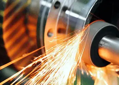
The final shape and dimensions of the gear are often achieved through machining. Gears can be improved overall by applying surface finishes like grinding and honing after they are manufactured.
Now, you must have gained a thorough understanding of gears, including their applications, specifications, and needs. You now know what kinds of gears your machine will require.
The performance and accuracy of gear parts have a direct impact on the stability and efficiency of numerous pieces of equipment used in modern manufacturing. Richconn is unique in being able to precisely complete these steps to ensure that every gear part meets the highest quality standards.
As a result, Richconn can provide high-quality and efficient gear part solutions for many equipment manufacturers. Richconn has state-of-the-art equipment, professional personnel, and excellent gear machining services. Their services not only enhance equipment performance but also progress the manufacturing sector overall. Richconn is unquestionably the best option if you're looking for a business that can manufacture gear parts effectively and of a high caliber.

Which are the best gears?
Depending on the specifications and needs, various types of gears are best suited for different functions. Spur gears are still the most often used gears, nevertheless. They are reasonably simple to make and attain excellent accuracy.
What distinguishes a sprocket from a gear?
a. Sprockets and gears are similar mechanical devices that facilitate the transfer of power since they both have teeth. Here are some significant variations between the two, though.
b. While rockets lock with a bicycle chain or military tank tracks, gear teeth interlock.
c. Rockets can only operate along a parallel axis, but gears can transmit torque in parallel, perpendicular, and other configurations.
d. Chain and sprocket function well for longer distances, while gears are better suited for short-distance transmission.
e. Torques are transmitted in opposing directions by gears. With rockets, however, the situation is the opposite.
What distinguishes pinions from gears?
The smallest gear is called the pinion when two gears are meshing together. A lot of the time, the pinion is the driver and the gear is the driver. When the pinion is the drive gear, there is a step-down drive that produces more torque but a lower speed output.
 What is Precision Grinding & Types, Materials, ProcessesNovember 27, 2023The so-called precision grinding process is to utilize fine-grained abrasive grains and micro-powder to process ferrous metals, hard and brittle materials, etc., in order to obtain high machining accuracy and low surface roughness values.view
 The Science of Black: Understanding the Chemistry Behind Surface TreatmentsDecember 4, 2023Black as a color has always captivated and fascinated humans. It is mysterious, elegant, and striking, making it a popular choice for various applications. From fashion and design to technology and en...view
 What Is Zinc Alloy? The Complete Basics to Get StartedOctober 8, 2023This article covers the information you need to watch out for in product design and part manufacturing when using zinc alloy. Take a deeper look into zinc alloy!view
 Drill and Tap Specification ChartNovember 17, 2023In CNC machining, the usual process is to use a drill bit to drill a hole in the workpiece and then use a tap of the appropriate size to cut the desired threads in the hole. This ensures that the threads match the design requirements and can ensure that the threads fit correctly with other components.view
 Basic Parts of CNC Lathe and Their MaintenanceOctober 20, 2023CNC lathes and steering centers are highly accurate and efficient automatic machine tools. The machine is equipped with a multi-station turret or power turret for a wide range of machining capabilities. It can handle linear cylinders, tilting cylinders, arcs and a variety of complex workpieces such as threads, grooves, worms, etc.view
 CNC Control Systems: Unraveling the Core of Computer Numerical ControlNovember 3, 2023Are you ready to delve into the heart of modern manufacturing technology? Welcome to the world of CNC Control Systems, where precision and automation meet to revolutionize industries.view
 EN
EN
 ru
ru 

