Tolerance is precise machining and design, the actual parameter values of the parts of the allowable amount of change, such as a certain part of the upper and lower limits were 100, 60, then its tolerance is 40; if the upper and lower limits were +100, -100, then its tolerance is 200.
Tolerance is the design and manufacture of machinery, the actual parameters of the part value of the allowable amount of change. Parts in the CNC machining manufacturing process, due to machine tool accuracy, tool wear, measurement errors and other reasons, it is not possible to limit the processing error of the part size within a certain range, the amount of change in the size of the provisions out.
1) Basic Size
Dimensions determined at the time of design based on the strength and structural requirements of the part.
2) Actual size
Dimensions obtained by measurement.
3) Limit dimensions
Two limit values that allow dimensional changes. It is determined using the basic size as a base. The larger of the two limit values is called the maximum limit size; the smaller one is called the minimum limit size.
4) Dimensional deviation (referred to as deviation)
A certain size minus its basic size of the algebraic difference. Dimensional deviation has:
Upper deviation = maximum limit size - basic size
Lower deviation = minimum limit size - basic size
Upper and lower deviations are collectively referred to as limit deviations. Upper and lower deviations can be positive, negative or zero.
The national standard stipulates that: the upper deviation of the hole is coded as ES, and the lower deviation of the hole is coded as EI; the upper deviation of the shaft is coded as es, and the lower deviation of the shaft is coded as ei.
(5) Size tolerance (referred to as tolerance)
The amount of variation in the allowable size.
Dimensional tolerance = maximum limit size - minimum limit size = upper deviation - lower deviation
Because the maximum limit size is always greater than the minimum limit size, that is, the upper deviation is always greater than the lower deviation, so the size tolerance must be positive.
6) Zero Line, Tolerance Zones and Tolerance Zone Diagrams
The zero line is a reference line used to determine the deviation in the tolerance band diagram, i.e. the zero deviation line. Usually the zero line represents the basic size. At the left end of the zero line marked with "0", "+", "-" sign, zero line above the deviation is positive; zero line below the deviation is negative.
Tolerance zone is a region bounded by two straight lines representing the upper and lower deviations, and the width and location of the tolerance zone are the two elements constituting the tolerance zone.
(7) Standard Tolerance and Standard Tolerance Grade
Standard tolerance is a national standard listed to determine the size of the tolerance zone of any tolerance. The standard tolerance grade is the grade that determines the degree of dimensional accuracy. Standard tolerance is divided into 20 levels, namely IT01, IT0, IT1 ~ IT18, indicating the standard tolerance, the Arabic numerals indicate the standard tolerance level, of which IT01 level is the highest, the level decreases in turn, IT18 level is the lowest. For a certain basic size, the higher the standard tolerance grade, the smaller the standard tolerance value, the higher the accuracy of the size.
8) Basic deviation
It is used to determine the upward or downward deviation of the tolerance band relative to the position of the zero line. Generally refers to the deviation close to the zero line, when the tolerance band is located above the zero line, its basic deviation for the lower deviation, when the tolerance band is located below the zero line, its basic deviation for the upper deviation.
In actual product design, reasonable determination of tolerance is the key to ensure that the product is manufactured with excellent quality, good performance and low cost. As for the determination of tolerance, there are basically the following three methods, the industry is often different tolerance determination methods (for the current level of most industries):
Calculation method: Precision instruments often refer to the design data, mechanical design manuals and other theories to carry out detailed manual calculations to determine the tolerance;
Analogy method: the product is slightly larger equipment manufacturing industry to determine the tolerance of most cases is based on actual past experience to determine (these experiences are after R & D sampling verification and product iteration summarized and accumulated);
Software-assisted method: there is the borrowing of tolerance determination software to determine the current application in the automotive industry more in the domestic manufacturing industry, most companies do not use this type of software. But this is the trend of the future!
Determine the tolerance, but also need to follow the tolerance principle. The principle of tolerance refers to the range of permissible deviations for elements such as size, shape and position in the manufacturing process, in order to ensure the interchangeability and functionality of the part. The purpose of the tolerance principle is to ensure that the parts match each other during assembly and use, and to ensure stability of their function and performance.

Independence of the principle of drawing given by the shape and position tolerance and dimensional tolerances independent of each other, respectively given, respectively measured, respectively to meet the requirements of a principle. It is mainly used for non-coordinated parts or strict requirements on shape and position, while the dimensional accuracy requirements are relatively low occasions.
There is no matching requirement for the element size, such as the external dimensions of the part, piping size, and process structure dimensions, such as the size of the retracting groove, thread closing, chamfering, chamfering dimensions, and so on, and there is no labeling of dimensional tolerances of the element size.
Inclusion requirement means that the actual element is located in the inclusion surface of the elevation shape, the size of the elevation shape is MMS (maximum solid size), then it should comply with the MMB (maximum solid boundary). It is mainly used where there is a fit requirement and the nature of the fit needs to be guaranteed.
The main reason for using the inclusion requirement is to ensure the nature of the fit, especially for precision fits with small fit tolerances. With the maximum solid boundary integrated control of the actual size and shape errors to ensure the necessary minimum clearance (to ensure free assembly) or maximum interference. With the smallest solid size control maximum clearance or minimum interference (interference fit), so as to achieve the required fit properties. Examples include the fit of rotary shaft journals and plain bearings, sliding sleeves and bores, slides and slide grooves, and so on.
The maximum solidity requirement is a tolerance principle that controls the actual contour of the measured element to be within the maximum solidity effectiveness boundary. That is, when the actual dimensions deviate from their maximum solid dimensions, the value of the form and position error can exceed the value of the form and position tolerance given on the drawing.
When MMR (Maximum Solid Requirement) is applied to the measured element, the form tolerance value of the element is given when the part is in MMC (Maximum Solid Condition); as long as MMR is applied, the Maximum Solid Boundary of Effectiveness must be observed; when the actual dimensions deviate from the MMVS (Maximum Solid Dimension of Effectiveness), the form error value is allowed to be compensated.
Maximum entity requirements are established from the basis of assembly interchangeability, commonly used in parts with low precision (dimensional accuracy, low form accuracy), with the nature of the requirements are not strict, but requires free assembly of parts to obtain the maximum benefit of technical managers, for example: control of screws, bolts, etc., the center of the distance between the location of the positional tolerances.
Minimum solid requirement is to control the actual contour of the measured elements in the LMVB (minimum solid validity boundary) within a tolerance principle. That is, when its actual size deviates from the LMS (Least Solid Size), the value of the form and position error can be compensated.
The minimum solid requirement is mainly used where the strength of the part or the minimum wall thickness is to be guaranteed. When LMR (Least Solid Requirement) is applied to a measured element, the shape tolerance value of the element is given when the part is in LMC (Least Solid Condition); whenever LMR (Least Solid Requirement) is applied, LMVB (Least Solid Viable Boundary) must be observed.
When its actual size is equal to the minimum solid size, the form and position tolerance is equal to the given value; when its actual size deviates from the minimum solid size, it is permitted to compensate the excess value to the form and position tolerance up to the value of its dimensional tolerance.
Reversible requirement is the premise of not affecting the function of the part, when the measured axis or the center plane of the form and position error value is less than the given value of the form and position tolerance allows the corresponding dimensional tolerance increase. In other words, it is permissible for the form tolerance to be compensated for the dimensional error (back-compensation).
Reversible requirements cannot be used alone, they are usually applied together with MMR (Maximum Solid Requirement) or LMR (Minimum Solid Requirement), when the measured element should comply with MMVB (Maximum Solid Boundary of Validity) or LMVB (Minimum Solid Boundary of Validity).
 CNC Machining Materials Guide: Selection, Applications, and Best PracticesNovember 6, 2023Are you ready to unlock the secrets of CNC machining materials and revolutionize your manufacturing process? If so, you've come to the right place. In this comprehensive guide, I'm going to walk you through everything you need to know about CNC machining materials. We'll explore the different types of materials, their characteristics, and the best practices for selecting and using them.view
 Unveiling the Wonders of Electrophoresis Metal Coating in Gel ElectrophoresisFebruary 29, 2024Gel electrophoresis, a foundational technique in the field of molecular biology, serves as a crucial tool for scientists to unravel the complexities of genetic material. At the heart of this precision...view
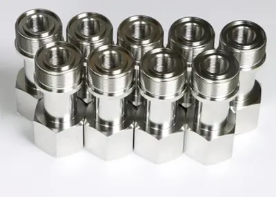 What Is Titanium? (Definition and Guide)February 26, 2024How to choose titanium for your project? Familiarize yourself with the various titanium grades and learn how to choose the most suitable grade for your needs.view
 Three Things You Need to Know About CNC Machining in the Energy IndustryOctober 25, 2023Before the Industrial Revolution, human beings didn't have much need for energy. For example, we were happy to use the sun's energy to heat our homes, horses for transportation, wind power to sail around the world, and water to power simple machines that ground grain.17 In the 1980s, everything changed with the rapid growth of steam-powered electric power plants, most of whose components were manufactured using high-speed machine tools.view
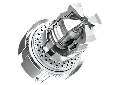 Unleashing Precision: Richconn's CNC Machined Steel ExcellenceNovember 10, 2023Welcome to the realm of precision and durability, where machined steel takes center stage. In this comprehensive exploration, we'll navigate through the intricacies of machined steel, unveil its diverse applications, compare various types, delve into performance metrics, examine Richconn's CNC machining advantages, and provide essential knowledge on mechanical machining.view
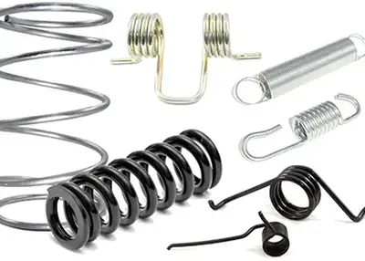 Unraveling the World of Machined Springs: Your Ultimate GuideNovember 9, 2023As a CNC machining service provider, we at Richconn understand the significance of precision engineering and how it's all about the details. In the realm of mechanical components, one topic that piques the curiosity of engineers, manufacturers, and professionals alike is -Machined Springs. In this comprehensive guide, I will walk you through the intricacies of Machined Springs, from the fundamentals to their applications, performance characteristics, manufacturing processes, and more.view
 EN
EN
 ru
ru 
