
In CNC machining, there are advances and improvements year after year. As a result, it is also becoming more complex. Consequently, it's also becoming more difficult to decide what to consider when designing parts. However, by making some relatively simple adjustments to part design and choosing the right material, costs can be reduced while improving the functionality of machined parts.
At Richconn, our engineers can get you a quote quickly. It can highlight features that require special consideration when designing for rapid manufacturing. Our engineers can find features that cannot be manufactured (or can only be manufactured with additional tooling and equipment), as well as areas that don’t necessarily need to be changed but whose design would make overall machining easier, such as inside corners, recessed characters, thin walls, deep holes and complex geometries, etc.
Below are some tips on how to design more cost-effective CNC parts.
Think about the corners of a CNC machined pocket - perhaps the inside of an electronics enclosure or a bracket for the housing of a rectangular component. Often overlooked in design is the fact that the cut lines of the vertical walls should form perfectly sharp inside corners. To illustrate this, think of machining a stainless steel box for playing cards. The only way to achieve truly square vertical corners that accurately enclose the cards is to EDM or screw multiple flat panels together. Both can be time-consuming and costly.
Instead, on one of our CNC machining centers, we chuck in the smallest end mill we have to mill out the corners. For 304 stainless steel, that's a 0.8-mm end mill, which leaves a corner radius of 0.4 mm. That's pretty sharp, but there are limitations on depth. The length, of most end mills for steel machining in this size range, is limited to five times the cutter diameter. Machining with small end mills like this is also a time consuming and delicate job, driving up the cost of your project due to the additional time required.

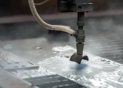
This illustration shows a undercut to achieve sharp inside corners, in this case on a stainless steel can for a baseball card collection. This achieves right-angled corners that perfectly enclose the cards
A more budget-friendly approach is to mill out a undercut on the inside corners. This eliminates the annoying rounding, and instead leaves a U- or C-shaped clearance. This also allows for much deeper pockets - if a 6.35 mm deep undercut is placed in each corner, functionally sharp corners up to 32 mm deep are possible. And by choosing aluminum or even plastic instead of steel, pocket depths can be doubled. Most importantly, however, part costs are reduced in this way, as larger end mills can be used and material removal rates increase accordingly.
Avoiding edge breakage is another cost-saving measure associated with radii. When trying to remove burrs and break sharp edges, designers often smooth external cut lines on parts by chamfering or rounding edges. This is understandable and sometimes necessary, but it can also be expensive. For metal parts, Richconn offers an automatic deburring option, and plastics are supplied in the machined raw state or with sharp edges as shown. If the design of a part requires an edge break, we need to use an additional tool (a ball end mill) and machine those corners with a 3D profiling motion of the machine.

To prevent burrs and break sharp edges, designers often try to bevel or round off outside edges, as you can see in the figure
We usually run these tools at high speeds, and small amounts of material are removed. Still, this is a lengthy process, as back and forth must be done until all edges are smooth. Many customers choose to save money by deburring these parts themselves with a file, some sandpaper or a sanding disc.
Similarly, recessed lettering, while aesthetically pleasing, requires a time-consuming process that should be avoided if possible. Again, a ball nose cutter is used to cut in the letters, numbers and symbols provided in the CAD model. Lettering looks cool and may be desired on machined parts for good reason, but it is probably more suitable for injection molded parts where the additional machining time is compensated for by larger quantities. Because of the respective tool sets, a minimum feature size of 0.90 mm for metal and 0.51 mm for plastic applies.
Our standard part tolerance is +/- 0.1 mm. Features with dimensions of 0.51 mm or below will be marked as thin wall geometry by our engineers. Note, however, that we still allow machining, and consequently the machined part may differ slightly from your original design. Thin walls of 0.51mm or less, run the risk of breaking during the machining process or bending or warping later. Reinforce them as best as your part design will allow.

Use caution with parts that have thin walls, as they may break during machining or bend afterwards. Reinforce them as best as your part design will allow
Very deep pockets should be avoided at all costs, even if the corners are undercut. Removing the material takes a lot of machining time. In addition, residual stress in the raw material becomes a problem as the pockets get deeper and the walls get higher. Angles or support structures could be used to strengthen these workpieces and prevent movement due to stress, but this again increases machining costs. The best advice for manufacturers or designers of machined parts is to keep the design as simple as possible.
The same principle applies to the overall geometry of the parts. Don't try to put too much on your parts. Maximizing the use of material can lead to problems in clamping and machining the part, resulting in higher costs. If the design becomes too complex, consider splitting into multiple components and assembling them with fasteners. No one is happy about assembly costs or the complexity that comes with multiple parts, but for parts that are difficult to machine, this might be the best solution. Especially when speed is important. Textured surfaces, cavities (think heat sinks), very deep holes (hydraulic manifolds) and threads are among the notorious machining cost drivers that can eat into your project budget.

Keep the design as simple as possible. If the design becomes too complex, consider splitting it into multiple components that can be bolted together
One of the easiest ways to stay within budget is to choose a more machine-friendly or less expensive material. Our material choices include various metals and plastics, each of which requires consideration of individual engineering properties, aesthetics, machining capabilities and material costs. Here are some important considerations in material selection:
# 17-4 PH stainless steel is difficult to cut. If high strength and corrosion resistance are not important, try 316L or 304 instead.
# Copper is an excellent electrical conductor, but more expensive than aluminum. While aluminum has about 60 percent of the electrical conductivity of copper, you might end up considering it because of the weight and cost savings.
# If hardness is important, 4140 might be your first choice, but 1018 is less expensive and case-hardens very well.
# Millers are always pleased with workpieces made of brass. A soft metal that is easy to mill and may have just the mechanical, chemical and conductivity properties needed for your application.
# Our selection of plastics includes nearly three dozen materials. All are relatively easy to cut. A factor that often means lower part costs. Some plastics offer superior wear, corrosion or chemical resistance. Others, are suitable for hot environments or open flames. And still others excel in strength, impact or electrical properties. As a rule, the softer the material, the greater the risk to dimensional accuracy and the risk of thread formation during milling.
Are you unsure which material to choose? Feel free to check out our full list of CNC machining materials.
When you upload a CAD model to our website, our engineers calculates what can be produced without problems and what comes with risks. The results are clearly presented in the quote. This gives you the opportunity to adjust the part design if necessary and have the costs recalculated. In case of doubt, please feel free to contact our application engineers or e-mail sales@richconn.com.cn at any time.
 What Is CNC Cutting? Unlocking the World of Precision MachiningNovember 2, 2023Are you intrigued by the world of precision manufacturing and curious about the fascinating technology behind it? If so, you've come to the right place. In this comprehensive guide, I'll take you on a journey through the realm of CNC Cutting, revealing its inner workings, diverse applications, and future trends.view
 Introduction to MetalworkingOctober 24, 2023Humans have developed many methods of metal fabrication, which is the processing of metal into various shape types. Here we will introduce some of the concepts and processes of this metal working method.view
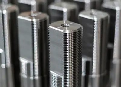 Broken Tap Extractor | How to Remove a Broken Tap (10 Methods)November 7, 2023When assembling parts, thread connections are commonly used, and tapping is necessary to create internal threads. Unfortunately, taps can break during the process. When a tap breaks inside a hole, you...view
 What is CNC Lathe Machining and Its Equipment Structure?October 20, 2023Lathe is the workpiece fixed on the spindle, high-speed rotation to process the tool feed movement of a machine tool. Lathe is driven by the motor through the belt and gear transmission system to drive the spindle rotation, driven by the spindle chuck on the workpiece rotation, and then use the fixed in the tool holder turning tool for turning machine tools.view
 Machinist Tools: What They Are, How to Use ThemDecember 1, 2023Machinist tools are a variety of products that are used to shape, cut, grind, shear, and form metal into a desired part. They are essential for metalworking and machining, which are the processes of creating metal products or components by removing metal chips in the workpiece.view
 Surface Finishing Process What Are the Different Products Suitable For What Process?October 24, 2023The whole process of processing, in the selection of the appropriate processing method CNC processing or 3D printing, after the completion of processing, most of them need surface treatment. Meet the corrosion resistance, abrasion resistance, decoration or other special functional requirements of the product.view
 EN
EN
 ru
ru 


")