
Are you designing metal parts? When you add metal CNC machining and 3D printing to your repertoire of manufacturing tools, you're not just more flexible when it comes to part design. You can also source them in less time and at a lower cost than ever before. To take advantage of this, however, it's important to understand what the common strengths and inherent differences of the processes are and how you can best leverage them to your advantage.
In no other area is the relationship more significant than between CNC machining and direct metal laser sintering (DMLS), the leading technology for 3D printing complex metal parts. With DMLS, virtually any shape can be imaged with nothing more than a laser beam and a pile of metal powder. However, the process can take some time. Machining, on the other hand, is more limited in terms of geometry, but offers much faster production speeds. Deciding which process to use depends primarily on two questions: A) Can the parts be produced by machining?, and B) How many parts are needed?
In many cases, the two manufacturing processes can complement each other. Here are a few examples. Often, metal-based additive manufacturing relies on its subtractive alter ego to get the job done. Holes need to be drilled or reamed, threads cut or CNC milled, and critical surfaces milled,CNC turned or ground to size. At the very least, however, 3D printed parts need some stroking in the form of cleaning, blasting and removal of support structures, which should make a visit to a precision machine shop a pretty safe bet.
3D printing and metal machining make a good pair for:
* Improving part accuracy
* surface finishing
* Machine elimination of support structures
* Clamping components, if necessary
What does all of this mean to you or anyone looking for the most efficient solution for producing working prototypes and small quantities of metal parts for end use? A lot. With a strategy where 3D printing and metal machining are distinct steps in the same manufacturing process, you can get the best of both worlds while avoiding nasty surprises, reducing costs and optimizing part design. Here are a few considerations to make before you embark on your next metal part manufacturing design project.
As mentioned at the beginning of this design tip, a good overview of each process is important. We know this is part of the general knowledge for many engineers. With that said, let's briefly go over it.
Of the five additive manufacturing technologies used at Richconn (and making up the lion's share of all 3D printing processes worldwide), DMLS is the only process used to print metal. As with any other powder bed-based printing process, this uses a laser (or multiple lasers) to fuse powder-sized metal granules in the machine's process chamber. Working from the bottom up, the machine fuses the paper-thin layers of the workpiece one by one. As it does so, a squeegee pulls the fresh powder over the surface after each step until the part is complete.

3D printing and CNC machining the yin and yang of metal fabrication.
Machining, on the other hand, removes metal using super-hard cutting tools, either by rotating the tool against and around a clamped workpiece (milling) or by moving a stationary cutting tool against and around a rotating workpiece (turning). There would be much more to say about the machining process. First, however, it is important to know that machining picks up where DMLS leaves off. In other words, while the DMLS process adds material in individual layers, machining removes material - sometimes large chunks, but sometimes very little - to create fine surfaces.
If you're designing metal parts, consider adding both CNC machining and 3D printing (direct metal laser sintering or DMLS) to your repertoire of manufacturing tools. It's no longer an either-or proposition, as the combination of subtractive and additive methods can help make metal manufacturing successful.
Although DMLS can be used to produce extremely complex shapes that would not be feasible by other means, this process also has its limitations. Quick info for newcomers: when working with lasers, the metal is first heated to a high temperature and then cools, causing residual stresses that must be removed via heat treatment after 3D printing. This tells the designers of the part little, except that the stress relief is associated with some part movement and therefore a loss of accuracy. This is one reason - though not the only one - why even the features of well-designed DMLS parts must be machined when tolerances of less than ±0.1 mm must be maintained.
Another reason to combine DMLS and machining is surface finishing. On a vertical or horizontal surface, the DMLS process produces parts with a roughness similar to sand casting. On all other surfaces, some step effect is visible, depending largely on the position of the part in the process chamber. If you need a smooth surface for your design, the part will need to be blasted, ground, or possibly machined. This last step is not much of a problem unless your design calls for a fine surface in places that cannot be reached with the end mill, drill, or turning tool. In any case, you should point out such critical features when you present your CAD model to Richconn so that features that need to be reworked by machine, for example, can be identified.
On a vertical or horizontal surface, direct metal laser sintering (DMLS) produces parts with a roughness similar to sand casting. On all other surfaces, some step effect is visible. If you need a smooth surface for your design, this step effect will need to be blasted, ground or machined (See below).

Support structures should also be considered when developing metal parts in additive manufacturing. DMLS can be roughly compared to building a sand castle: without a few shells and branches to hold it all together, the ramparts and castle gates will collapse. In the DMLS process, scaffold-like structures are needed to prevent the semi-molten metal from sagging, curling or otherwise behaving in undesirable ways. Often these support structures can be removed with a Dremel. Machining, however, may be the preferred method when larger quantities of parts are needed or when the part must go to the machine shop anyway for any of the previously mentioned turning, drilling, or milling operations.
Unlike the DMLS process, which requires only a simple build platform on which the part sits until it is finished, machined parts must be clamped, bolted or otherwise securely fastened to the machine to prevent movement caused by the cutting tool. How can the machinist best clamp a 3D printed part that consists entirely of curved, organic shapes (which makes 3D printing particularly attractive) for turning or milling? Consult with a Richconn applications engineer. You may need to include a few parallel surfaces or mounting holes in your design that will allow you to clamp the 3D printed part for machining.
Clamping of printed parts is often necessary. This requires adding a tab or other fixture to the CAD model and printing it directly to the part, as seen here. It can be removed again after machining.

Tabs when clamping printed parts
Last but not least, you should make considerations about the metal. The lasers used in the DMLS process have no problem with hard or robust metals, but cutting tools do. The DMLS process is known to print metals suitable for medical and aerospace applications, such as titanium, Inconel and others, because it handles different laser parameters and build speeds relatively well. Machining these metals, on the other hand, requires shallower depths of cut, slower speeds and feeds (and to use the technical jargon), and is associated with higher tool wear and longer machining time. For all of Richconn's options for machining and 3D printing with metal, see the Materials Comparison Guide. In addition to a listing of materials, you will find other material-related questions in this guide. For example, if Richconn does not machine a specific material, this does not necessarily mean that we do not offer post-processing for this material in 3D printing. For such specific questions, please contact one of our application engineers at +86-0755-28025755 0 or at sales@richconn.com.cn.
This is what matters: For metal parts, you can actually get the best of both worlds - 3D printing and machining. However, carefully review the options in this design tip. Machining and metal 3D printing are highly complex technologies. Only when you understand how they affect your design project will you achieve the success you want. Ask questions, embrace each process, and recognize that both are close partners in manufacturing.
If you have a design for a metal part that could benefit from the combination of 3D printing and CNC machining, be sure to indicate that during the 3D printing quote process. When uploading a CAD file, select the option for custom finishes and indicate in comments which features or finishes require additional surface treatment. You can also attach documents, such as a drawing, to specify tolerances, surface finishes, and other manufacturing requirements.
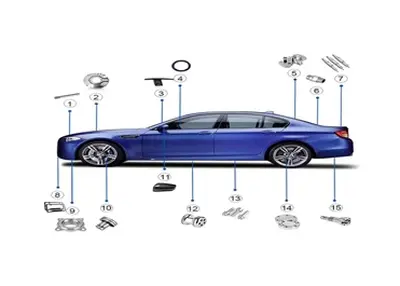 How CNC Automotive Parts Elevate Vehicle FunctionalityJanuary 5, 2024When it comes to the automotive industry, precision and performance are of utmost importance. Manufacturers are constantly striving to enhance the functionality of vehicles, which relies heavily on th...view
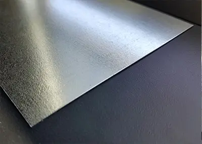 Galvanized Sheet Metal: Unveiling the Power of a Versatile MaterialSeptember 28, 2023When it comes to construction and engineering, one material that stands out for its versatility and durability is galvanized sheet metal. In this comprehensive guide, I will take you on a journey through the world of galvanized sheet metal, exploring its various facets, applications, and even its synergy with CNC technology.view
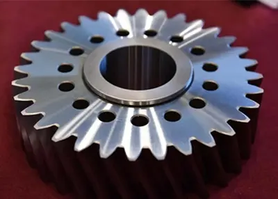 Types of Gears: An Overview of Various Mechanical GearsApril 26, 2024This article is about important information you need to know about gears, including types of gears, applications, production and advantages and disadvantages.view
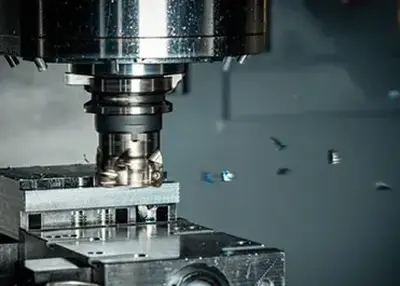 What is face milling?November 22, 2023Face milling is a metalworking process that is widely used in manufacturing and machining. It is a process in which the surface of a workpiece is cut by a milling cutter on a milling machine to obtain the desired shape, size and surface quality. Face milling can be used to process a variety of metallic and non-metallic materials, including steel, aluminum, copper, plastics and so on.view
 7 Tips for Choosing a Right CNC Machine ManufacturerSeptember 7, 2023Some companies seek a quality precision manufacturer with the best matching services. Nowadays, there are lots of CNC manufacturers to choose from. The problem is how to pick out the right CNC manufac...view
 Top 12 CNC Machining Manufacturers in ChinaJune 6, 2024Among the numerous CNC machining services, why choose CNC machining manufacturers in China for your projects? This article will reveal the answer for you.view
 EN
EN
 ru
ru 


")