Engineering drawings are a graphical language used to express engineering design ideas and details, and they are an important tool for engineers for design, manufacturing and maintenance. Engineering drawings follow a number of international or national standards and specifications to ensure the accuracy, consistency and readability of engineering drawings. In this paper, we will introduce the definition, purpose, types and application areas of engineering drawings, as well as the basic elements of engineering drawings, how to draw them, how to read them, and common problems and solutions.
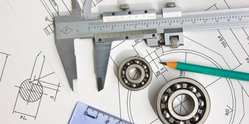
Engineering drawing is a graphical language used to express engineering design ideas and details, which is an important tool for engineers for design, manufacturing and maintenance. Engineering drawings follow some international or national standards and specifications to ensure the accuracy, consistency and readability of engineering drawings. In this article, we will introduce the definition, purpose, types and application areas of engineering drawings, as well as the basic elements of engineering drawings, how they are drawn, how they are read, and common problems and solutions.
An engineering drawing is a type of drawing that represents the shape, size, location, surface condition, material, processing requirements, and other relevant information of an engineering object by means of graphic symbols, text, and figures https://s3vi.ndc.nasa.gov/ssri-kb/static/resources/Engineering+Working+ Drawing+Basics.pdf. Engineering drawings are the communication medium between engineers and other related personnel, which can help engineers clearly express their design intent, and can also help manufacturing personnel, inspectors, maintenance personnel, etc. to correctly understand and implement the engineer's design requirements.
The main purpose of engineering drawings is to visualize, transmit and document engineering design. Engineering drawings enable engineers to better visualize and analyze the structure, function, and performance of engineering objects during the design process, as well as enable engineers to communicate and collaborate effectively with other relevant personnel, and to preserve and manage the history and version of engineering designs. Engineering drawings can also be used as a basis and reference for the manufacture, inspection, maintenance and use of engineering objects.
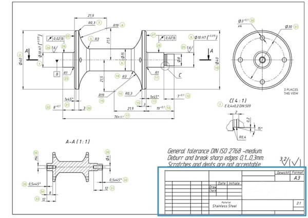
There are many types of engineering drawings, which can be categorized into different categories based on different classification criteria. The following are some common types of engineering drawings:
- According to the content and use of engineering drawings, they can be categorized into design drawings and working drawings. Design drawings are drawings used by engineers to express and verify design ideas during the design process, which usually contain information about the shape, size, location, structure, function and performance of the engineering object, but do not necessarily contain all the details and requirements. Working drawings are used by engineers to guide the manufacture, inspection, maintenance and use of engineering objects after the completion of the design, which usually contains all the details and requirements of engineering objects, as well as related standards and specifications. Working drawings can be further categorized into parts drawings, assembly drawings, installation drawings, etc., according to the different components and stages of the engineering object.
- According to the method of drawing engineering drawings, they can be categorized into hand drawing and computer-aided drawing. Hand drawing is a drawing drawn on paper with hand tools such as pencil, ruler, compass, etc. It is the traditional method of drawing engineering drawings, but it has been gradually replaced by computer-aided drafting. Computer-aided drafting is the drawing drawn on the computer screen with computer software, such as AutoCAD, SolidWorks, CATIA, etc. It is the modern method of engineering drawing, which has the advantages of high efficiency, accuracy, flexibility and easy modification, and it can also be exchanged and integrated with other computer software for data exchange.
- According to the principle of drawing engineering drawings, it can be divided into plane projection method and axonometric projection method. Plane projection method is to use parallel projection lines to project the three-dimensional shape of the engineering object onto one or more vertical projection surfaces, so as to get the two-dimensional view of the engineering object drawings, it is the most commonly used engineering drawing method, it can maintain the true size and proportion of the engineering object, but also can be used in different projection methods and view combinations to represent different aspects of the engineering object. Axonometric projection is a drawing that uses an inclined projection line to project the three-dimensional shape of an engineering object onto an inclined projection plane, thus obtaining a three-dimensional view of the engineering object. It is an auxiliary method of drawing engineering drawings, which can represent the overall shape of an engineering object in a more intuitive way, but it can cause deformation of the dimensions and proportions of the engineering object, and is not easy to carry out dimensional dimensioning and detail description.
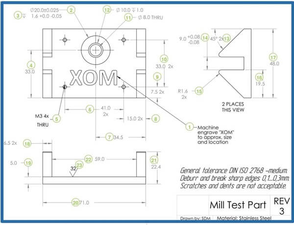
Engineering drawings have a wide range of application areas, covering almost all engineering disciplines and industries. The following are some of the common application areas of engineering drawings:
Mechanical engineering refers to the engineering discipline of studying and designing various mechanical devices and systems, which involves mechanical structure, mechanical motion, mechanical mechanics, mechanical materials, and mechanical manufacturing. Commonly used engineering drawings in mechanical engineering are mechanical parts drawings, mechanical assembly drawings, mechanical installation drawings, mechanical schematic drawings, mechanical process drawings, etc. They are used to express the shape, size, location, structure, function, performance, processing requirements and methods of use and other information of mechanical equipment and systems.
Electrical engineering refers to the engineering discipline of researching and designing all kinds of electrical equipment and systems, which involves circuits, electromagnetism, power, electronics, communication, control and so on. Commonly used engineering drawings in electrical engineering are electrical component diagrams, electrical connection diagrams, electrical wiring diagrams, electrical schematic diagrams, electrical control diagrams, etc. They are used to express information about the shape, size, location, structure, function, performance, connection requirements and control methods of electrical equipment and systems.
Civil engineering refers to the engineering discipline of studying and designing various buildings and infrastructures, which involves structures, materials, geology, water resources, transportation, and the environment. Commonly used engineering drawings in civil engineering include architectural plan, architectural elevation, architectural section, architectural structure, architectural construction, architectural equipment, road, bridge, tunnel, water conservancy, drainage, etc. They are used to express information about the shape, size, location, structure, function, performance, construction requirements, and methods of use of buildings and infrastructures.
Chemical engineering refers to the engineering discipline of studying and designing various chemical processes and equipment, which involves chemical reactions, transfer phenomena, separation techniques, catalysts, biotechnology, and so on. Commonly used engineering diagrams in chemical engineering are chemical flow chart, chemical device diagram, chemical piping diagram, chemical instrumentation diagram, chemical reactor diagram, chemical tower diagram, chemical separation diagram and so on, which are used to express the shape, size, location, structure, function, performance, connection requirements and control methods and other information about chemical processes and equipments.
In addition to the above few common application areas of engineering drawings, there are many other application areas of engineering drawings, such as aerospace engineering, automotive engineering, marine engineering, nuclear engineering, medical engineering, agricultural engineering, etc., which have their own types and specifications of engineering drawings used to express the characteristics and requirements of their respective engineering objects.
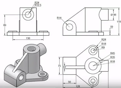
Engineering drawings contain many basic elements used to represent information about engineering objects, such as lines, symbols, scales, dimensioning, tolerances and accuracies. These basic elements have certain meanings, forms and rules, and engineers need to follow the standards and specifications of these basic elements when drawing and reading engineering drawings to ensure the clarity, accuracy and consistency of engineering drawings.
Lines are the most basic elements in engineering drawings, which are used to represent the outline of engineering objects, boundaries, centers, symmetry, axes, projections, profiles, sections, hidden lines and so on. The type, thickness, spacing and length of the line have certain provisions, different types of lines indicate different meanings, as shown in the table below:
| Line Type | Line Form | Line Meaning |
|---|---|---|
| Solid Line | —— | Represents the visible outline or boundary of the engineering object |
| Dashed Line | - - - | Represents the invisible outline or boundary of the engineering object |
| Center Line | - · - · - | Represents the center, symmetry or axis of the engineering object |
| Projection Line | —— | Represents the projection or correspondence between the views of the engineering object |
| Section Line | \\\ | Represents the section or cut of the engineering object |
| Assembly Line | - - - - | Represents the assembly or disassembly order of the engineering object |
| Dash Line | — — — | Represents the equal distance in the same plane of the engineering object |
| Long Chain Line | —— · —— · —— | Represents the auxiliary line or reference line of the engineering object |
| Arrow Line | ——> | Represents the direction, position or dimension annotation of the engineering object |
Lines in engineering drawings should be clear, neat and well-proportioned, and should not have breaks, crosses, overlaps, etc., so as not to cause confusion or misunderstanding. Lines in engineering drawings should also be arranged according to a certain priority. Generally speaking, solid lines take precedence over dashed lines, dashed lines take precedence over center lines, center lines take precedence over section lines, section lines take precedence over long chain lines, long chain lines take precedence over short scribed lines, and short scribed lines take precedence over assembly lines.
Symbols are graphical markings used in engineering drawings to indicate some special information about engineering objects, such as surface states, materials, welds, threads, gears, springs, bearings, and so on. The shape, size and position of symbols have certain regulations, and different symbols indicate different meanings, as shown in the table below:
| Symbol Type | Symbol Form | Symbol Meaning |
|---|---|---|
| Surface State Symbol | ▽ | Indicates that the surface of the engineering object needs to be polished |
| Material Symbol | ○ | Indicates that the material of the engineering object is steel |
| Welding Symbol | ∠ | Indicates that the two parts of the engineering object need to be angle welded |
| Thread Symbol | ∥ | Indicates that the part of the engineering object has a thread |
| Gear Symbol | ⊙ | Indicates that the part of the engineering object has a gear |
| Spring Symbol | ~ | Indicates that the part of the engineering object has a spring |
| Bearing Symbol | ◇ | Indicates that the part of the engineering object has a bearing |
Symbols in engineering drawings should be concise, clear and uniform, and there should be no redundant or ambiguous symbols to avoid confusion or misunderstanding. Symbols in engineering drawings should also be placed according to a certain position and direction. Generally speaking, symbols should be placed near the corresponding part of the engineering object, and the direction of the symbols should be consistent or perpendicular to the direction of the engineering object.
Scale is a numerical value or graphic mark used in engineering drawings to indicate the proportional relationship between the actual size of the engineering object and the drawing size, such as 1:10, 1/10, 10:1, 10/1 and so on. There are certain regulations for the selection and representation of scale, and different scales indicate different degrees of scaling, as shown in the table below:
| Scale Type | Scale Value | Scale Meaning |
|---|---|---|
| Reducing Scale | 1:10, 1/10, 1:100, 1/100, etc. | Indicates that the drawing size of the engineering object is smaller than the actual size, used for drawing large-scale engineering objects. |
| Uniform Scale | 1:1, 1/1 | Indicates that the drawing size of the engineering object is equal to the actual size, used for drawing medium-sized engineering objects. |
| Enlarging Scale | 10:1, 10/1, 100:1, 100/1, etc. | Indicates that the drawing size of the engineering object is larger than the actual size, used for drawing small-scale engineering objects. |
Scales in engineering drawings should be reasonable, consistent, and obvious, and there should be no inappropriate or inconsistent scales that could cause errors or variations in dimensions. The scale in the engineering drawings should also be labeled according to a certain location and format, in general, the scale should be placed in the lower right corner of the engineering drawings, the scale should be formatted as "Scale: Value" or "SCALE: Value".
Dimension labeling is used in engineering drawings to indicate the length, width, height, diameter, angle and other numerical values of the parts of the project object text or graphic markings, such as 10mm, 30 °, R5 and so on. There are certain regulations for the selection and representation of dimension markings, and different dimension markings indicate different types of dimensions, as shown in the table below:
| Dimension Annotation Type | Dimension Annotation Form | Dimension Annotation Meaning |
|---|---|---|
| Linear Dimension | 10mm, 20mm, 30mm, etc. | Represents the length, width, height, etc., of various parts of the engineering object. |
| Angular Dimension | 30°, 45°, 60°, etc. | Represents the angles, inclinations, or rotations of various parts of the engineering object. |
| Circular Dimension | ∅10mm, ∅20mm, ∅30mm, etc. | Represents the diameter, radius, circumference, etc., of various parts of the engineering object. |
| Arc Dimension | R5, R10, R15, etc. | Represents the arc length, radians, curvature, etc., of various parts of the engineering object. |
Dimensioning in engineering drawings should be complete, accurate, clear, and reasonable, and there should be no omissions, repetitions, errors, or conflicting dimensioning to avoid errors or changes in dimensions. Dimensioning in engineering drawings should also be marked in accordance with a certain location, direction, format and order, in general, the dimensioning should be placed on the view of the project object, the direction of the dimensioning should be the same as the direction of the project object or horizontal, the format of the dimensioning should be "numerical value + units + symbols", the sequence of dimensioning The order of dimensioning should be from overall to local, from big to small, from major to minor.
Tolerance and precision is used in engineering drawings to indicate the permissible deviation of the size of the object and the required precision of the numerical or graphical markings, such as ± 0.1mm, H7, 0.01mm and so on. Tolerance and accuracy of the selection and representation of certain provisions, different tolerances and accuracy of different deviations and accuracy levels, as shown in the table below:
| Tolerance and Precision Type | Tolerance and Precision Form | Tolerance and Precision Meaning |
|---|---|---|
| Linear Tolerance | ±0.1mm, ±0.01mm, ±0.001mm, etc. | Represents the difference between the upper and lower limits of the linear size of an engineering object. |
| Angular Tolerance | ±1°, ±0.5°, ±0.1°, etc. | Represents the difference between the upper and lower limits of the angular size of an engineering object. |
| Circular Tolerance | ∅10±0.1mm, ∅20±0.01mm, ∅30±0.001mm, etc. | Represents the difference between the upper and lower limits of the circular size of an engineering object. |
| Arc Tolerance | R5±0.1mm, R10±0.01mm, R15±0.001mm, etc. | Represents the difference between the upper and lower limits of the arc size of an engineering object. |
| Hole Basis Tolerance | H7, H8, H9, etc. | Represents the difference between the upper and lower limits of the hole size of an engineering object, as well as the fit with the shaft. |
| Shaft Basis Tolerance | h7, h8, h9, etc. | Represents the difference between the upper and lower limits of the shaft size of an engineering object, as well as the fit with the hole. |
Tolerances and accuracies in engineering drawings should be appropriate, consistent and obvious, and should not be too large or too small, so as not to cause the performance or quality of engineering objects. Tolerance and precision in engineering drawings should also be marked in accordance with a certain location and format, in general, tolerance and precision should be placed on the top or bottom of the size labeling, tolerance and precision format should be "numerical value + units + symbols" or "symbols + numerical value + units The format of tolerance and precision should be "value + unit + symbol" or "symbol + value + unit".
There are two methods of drawing engineering drawings, one is hand drawing and the other is computer-aided drawing. Hand drawing is a drawing made on paper using hand tools such as pencil, ruler, compass, etc. It is the traditional method of drawing engineering drawings, but it has been gradually replaced by computer-aided drafting. Computer-aided drafting is to use computer software, such as AutoCAD, SolidWorks, CATIA, etc., drawings drawn on the computer screen, it is a modern method of engineering drawing, which has the advantages of high efficiency, accuracy, flexibility and easy modification, and can also be exchanged and integrated with other computer software for data exchange.
Hand drawing is to use hand tools, such as pencils, rulers, compasses, etc., drawings drawn on paper, it is the traditional method of engineering drawing, but has been gradually replaced by computer-aided drafting. The advantages of hand drawing are simple, convenient, economical, no special equipment and technology, suitable for preliminary design sketches and simple engineering drawings. The disadvantages of hand drawing are low efficiency, poor accuracy, difficult to modify, difficult to save, not suitable for complex engineering drawings and a large number of engineering drawings.
The steps of hand drawing are as follows:
- Prepare tools: Prepare tools such as pencils, erasers, rulers, compasses, triangles, drawings, etc., choose the right line thickness and color, choose the right size and format of the drawing.
- Drawing frame: use a ruler and pencil to draw a rectangular frame on the drawing, the size of the frame should leave a certain margin, the location of the frame should be centered horizontally and vertically.
- Drawing title bar: draw a small rectangular title bar in the lower right corner of the frame, the size of the title bar should occupy about 10% of the frame, the content of the title bar should include the name of the project drawings, numbering, scale, date, author, reviewer and other information, the format of the title bar should be filled out in accordance with the standards and norms.
- Drawing views: according to the shape, size, location and requirements of the project object, select the appropriate projection method and view combination, use ruler, compass, triangle board and other tools to draw each view of the project object in the drawing frame, the position of the view should be arranged in accordance with the corresponding relationship of the projection line, the size of the view should be adjusted in accordance with the scale of the scaling ratio, and the spacing of the view should be consistent and appropriate. The spacing of the views should be consistent and appropriate.
- Drawing dimensions: According to the size, tolerance and accuracy of the project object, choose the appropriate type of dimension and the location of the dimension, and draw dimension lines, dimension symbols and dimension values on the view with tools such as rulers, compasses and triangular boards, etc. The location of dimensions should be avoided to overlap or cross the lines and symbols, and the direction of dimensions should be the same as the direction of the view or horizontal, and the format of the dimensions should be in accordance with the standard and the format of the projection lines. The format of dimensioning should be written in accordance with the standards and specifications, and the order of dimensioning should be from overall to local, from big to small, and from major to minor.
- Drawing symbols: according to the surface state of engineering objects, materials, welding, threads, gears, springs, bearings and other special information, select the appropriate type of symbols and symbols position, draw symbols on the view with tools such as rulers, compasses, triangles, etc., the symbols position should be close to the corresponding part of the engineering objects, and the direction of the symbols should be consistent or perpendicular to the direction of the engineering objects, the The format of the symbols should be written according to standards and specifications.
- Checking and modification: Check the completeness, accuracy, clarity and reasonableness of the engineering drawings, find the mistakes or deficiencies, erase them with eraser or cover them with white paper, redraw or modify them until the engineering drawings meet the requirements.
Computer-aided drafting is the use of computer software, such as AutoCAD, SolidWorks, CATIA, etc., drawings drawn on the computer screen, it is a modern method of engineering drawing, which has the advantages of high efficiency, accuracy, flexibility and ease of modification, and can also be exchanged and integrated with other computer software for data exchange. The advantages of computer-aided drafting are high efficiency, high accuracy, easy to modify, easy to save, suitable for complex engineering drawings and a large number of engineering drawings. The disadvantage of computer-aided drafting is that it requires special equipment and technology, and is not convenient for preliminary design sketches and simple engineering drawings.
The steps of computer-aided drafting are as follows:
- Prepare the software: Prepare the computer, monitor, mouse, keyboard, printer and other equipment, install computer-aided drafting software, such as AutoCAD, SolidWorks, CATIA, etc., select the appropriate software version and settings, familiarize yourself with the interface and functions of the software.
- Create files: create a new file in the computer-aided drafting software, select the appropriate file type and format, such as DWG, DXF, PDF, etc., select the appropriate drawing size and scale, such as A4, A3, 1:10, 1:100, etc., select the appropriate units and precision, such as mm, cm, m, 0.1mm, 0.01mm etc.
- Drawing frame: use drawing tools in computer-aided drafting software, such as straight lines, rectangles, circles, etc., to draw a rectangular frame on the drawing, the size of the frame should leave a certain margin, the position of the frame should be centered horizontally and vertically.
- Drawing title bar: in the computer-aided drafting software using drawing tools, such as straight lines, rectangles, circles, etc., in the lower right corner of the drawing box to draw a small rectangle of the title bar, the size of the title bar should occupy the frame of the 10% or so, the contents of the title bar should include the name of the project drawings, numbering, scale, date, author, reviewer, and other information, the format of the title bar The format of the title bar should be filled out in accordance with the standards and norms, and the content of the title bar should be written using text tools, such as text, font, font size and so on.
- Drawing views: Use drawing tools in computer-aided drafting software, such as straight lines, rectangles, circles, polygons, curves, spline, etc., to draw the views of engineering objects in the drawing box, the positions of the views should be arranged in accordance with the corresponding relationship of the projection line, the size of the views should be adjusted in accordance with the scale of the scale, and the spacing of the views should be maintained consistently and appropriately. The spacing of the views should be consistent and appropriate. There are two ways to draw the views, one is to use drawing tools directly to draw the views according to the shape, size, location and requirements of the engineering object, the other is to use 3D modeling tools to create a 3D model of the engineering object first, and then use projection tools to generate the views of the engineering object.
- Drawing size annotation: use annotation tools in computer-aided drafting software, such as linear annotation, angle annotation, circular annotation, arc annotation, hole base annotation, shaft base annotation, etc., to draw size lines, size symbols, and size values on the view, the location of the size annotation should be avoided to overlap or cross with the lines and symbols, and the direction of the size annotation should be the same as the direction of the view or horizontal, the format of dimensioning should be written in accordance with the standards and specifications, and the order of dimensioning should be from overall to local, from big to small, and from major to minor.
- Drawing symbols: Use symbol tools in computer-aided drafting software, such as surface state symbols, material symbols, welding symbols, thread symbols, gear symbols, spring symbols, bearing symbols, etc., to draw symbols on the view, the position of the symbols should be close to the corresponding part of the engineering object, the direction of the symbols should be consistent with the direction of the engineering object or perpendicular to the direction of the symbols, the format of the symbols should be written in accordance with standards and specifications. The format of symbols should be written in accordance with standards and specifications.
- Check and modify: Check the completeness, accuracy, clarity and reasonableness of the engineering drawings, find the mistakes or deficiencies, use the modification tools, such as deleting, moving, rotating, scaling, copying, pasting, undoing, redoing, etc., to redraw or modify until the engineering drawings meet the requirements.
- Save and Print: Save the files of engineering drawings, choose the appropriate file name, file location, file type and file format, such as DWG, DXF, PDF, etc. Print the drawings of engineering drawings, choose the appropriate printer, print paper, print range, print ratio, print direction, etc., and check the effect of the printing, such as clarity, alignment and color.
Engineering drawings are a graphical language used to express the ideas and details of engineering design and it is an important tool for engineers for design, manufacturing and maintenance. Engineering drawings follow some international or national standards and specifications to ensure the accuracy, consistency and readability of engineering drawings. This paper describes the definition, purpose, types and application areas of engineering drawings, as well as the basic elements of engineering drawings, how they are drawn, how they are read, and common problems and solutions. This paper aims to help readers understand and master the basic principles and techniques of engineering drawings in order to improve the quality and efficiency of engineering design.
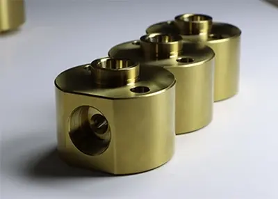 Brass vs Bronze vs Pure Copper vs Copper Alloys: An in-depth look at their differencesSeptember 26, 2023The comparison of brass to bronze to copper and its copper alloys is crucial as these metals can be easily confused. In addition, the distinction between these materials is also very subtle. As a result, development engineers or designers can be seriously confused when it comes to material selection. In particular, the similarity of these metal constituent elements makes it more difficult to classify and select them.view
 Passivation 101: What Is Passivated Stainless Steel and Is It Necessary?December 8, 2023Passivation enhances stainless steel’s durability and longevity by removing iron and forming a protective film layer. Here’s a basic guide to passivation of stainless steel.view
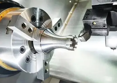 Challenge the Production of Mirror Discharge Mold Parts with H2 Grade Machining AccuracyMarch 2, 2023Challenge time: February 2023Challenge location: Longhua, Shenzhen, ChinaCustomer information: Singaporean high-quality mold vendorsNo nonsense, first upload the customer photo:Customer physical photo...view
 Revolutionizing Automotive Manufacturing with CNC Cutting Aluminum SheetsFebruary 29, 2024The Rise of CNC Cutting in Automotive ManufacturingIn the fast-paced world of automotive manufacturing, precision and efficiency are key factors that can make or break a company's success. One tec...view
 Richconn 2024 Chinese New Year Holiday NoticeJanuary 2, 2024January 02, 2024Chinese New Year is approaching! We would like to remind you that Richconn will be on holiday to celebrate our Chinese New Year. For your convenience in arranging your project, please ...view
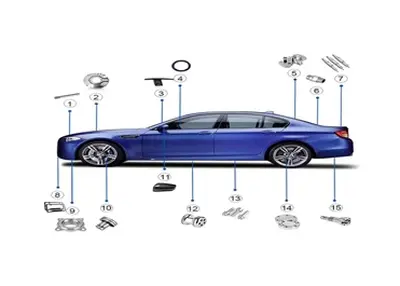 The Precision of CNC Automotive Parts in Gear SystemsJanuary 5, 2024In the world of automotive manufacturing, precision and reliability are crucial for the smooth operation of gear systems. As technology advances, the demand for precision components in the automotive ...view