
Are you ready to delve into the world of precision engineering? Let's embark on a journey to unravel the intricacies of roundness, its symbiotic relationship with GD&T, and the cutting-edge techniques defining its measurement standards.

Precision engineering stands as the cornerstone of modern industrial production. At its core lies the concept of roundness, an essential attribute that defines the quality and functionality of engineered components. To truly grasp the implications and applications of roundness in engineering, it's crucial to delve deeper into its multifaceted nature.
Roundness isn't merely about being circular; it embodies a meticulous standard governing the deviation of an object's form from a perfect circle. It's a quantitative measure that determines how closely an object approaches circularity. Factors such as machining processes, material properties, and environmental conditions significantly influence roundness.
In engineering, achieving high roundness is imperative for seamless functionality and reliability of various mechanical systems, from bearings and shafts to gears and cylinders. The permissible deviation from a perfect circle is governed by stringent standards and tolerances, often articulated using Geometric Dimensioning and Tolerancing (GD&T) principles.
The significance of roundness in engineering cannot be overstated. Its influence reverberates across diverse industries, impacting performance, longevity, and efficiency. For instance, in automotive manufacturing, the roundness of engine components directly influences engine performance and fuel efficiency. Similarly, in aerospace engineering, roundness is critical in ensuring the structural integrity and aerodynamic performance of components.

Machining processes play a pivotal role in determining the roundness of components. Variations in CNC turning machining , CNC milling machining , grinding, and other machining techniques directly impact the final form and roundness of the produced parts. Controlling parameters like tool wear, feed rates, and cutting forces becomes crucial in achieving desired roundness levels.
Material characteristics such as elasticity, thermal expansion, and ductility also contribute to roundness variations. Differential material responses to machining and environmental conditions can cause distortions, affecting the final roundness of the component.
Environmental factors like temperature, humidity, and vibrations can introduce distortions in manufactured parts. Minimizing these effects through controlled environments or compensatory measures becomes essential to maintain roundness standards.
International standards bodies such as ISO and ANSI define permissible limits for roundness in engineering components. These standards, often specified using GD&T symbols, outline the acceptable deviations from an ideal circle and provide guidelines for engineers and manufacturers.
The impact of roundness extends to various applications. For instance, in the medical field, precision roundness in prosthetic implants ensures proper fit and functionality, reducing the risk of complications. In precision optics, roundness directly affects the performance of lenses and optical systems.

Geometric Dimensioning and Tolerancing (GD&T) acts as the language of engineering, providing a standardized system to define and communicate dimensional tolerances. Within this framework, specific symbols are dedicated to articulating roundness specifications.
The roundness symbol, often represented as a circle with arrows indicating the circular form, elucidates the permissible deviations from an ideal circle. It outlines the maximum boundary within which the actual geometry of a circular feature must fall, ensuring precision in manufacturing processes.
GD&T specifications not only quantify the permissible deviations but also detail the method of measurement and assessment for roundness. Engineers rely on these symbols to convey design intent accurately to manufacturers and inspectors, ensuring compliance with stringent quality standards.
Historically, measuring roundness relied on instruments like dial indicators, micrometers, and coordinate measuring machines (CMMs). While effective for simpler geometries, these methods often lacked the precision required for complex shapes and tight tolerances.
The evolution of metrology has ushered in advanced techniques such as optical profilometry, laser scanning, and coordinate measuring machines equipped with high-precision probes. These cutting-edge technologies offer unparalleled accuracy, capturing intricate details of complex surfaces and enabling precise roundness measurements.
Circularity refers to the ideal state of being a perfect circle, emphasizing the absence of deviations or variations. Roundness, on the other hand, acknowledges the permissible deviations within defined tolerances from this ideal circular form.
Understanding the differences between circularity and roundness is crucial for engineers. While circularity serves as a theoretical benchmark, roundness accommodates the practical realities of manufacturing, allowing for controlled variations essential for functional components.
Traditionally, engineers relied on instruments like dial indicators and micrometers for roundness measurement. While these methods provided accurate results for simpler shapes, they struggled to capture the complexities of intricate geometries. Coordinate measuring machines (CMMs) were a significant advancement, offering a comprehensive approach but still facing limitations in precision for demanding applications.
The challenges with traditional methods included limited accuracy, time-consuming processes, and difficulty in capturing subtle deviations in intricate components. As engineering demands grew more sophisticated, a shift towards advanced measurement technologies became imperative.
The advent of optical profilometry, laser scanning, and high-precision probes marked a revolutionary leap in roundness measurement. Optical profilometry utilizes non-contact methods, capturing 3D surface profiles with exceptional precision. Laser scanning, employing laser beams to measure surfaces, enhances speed and accuracy. High-precision probes integrated into CMMs provide meticulous point-by-point measurements, overcoming the limitations of traditional methods.
In the aerospace industry, the demand for high-precision components is non-negotiable. Roundness measurements using advanced techniques ensure the integrity of critical components like turbine blades, where deviations could lead to catastrophic failures.
In automotive manufacturing, precision is paramount for components like engine cylinders and crankshafts. Advanced roundness measurement guarantees optimal performance, fuel efficiency, and reduced wear and tear.
In the medical field, the precision of prosthetic implants directly correlates with patient well-being. Advanced roundness measurement ensures a perfect fit, reducing the risk of complications and enhancing the longevity of implants.
The integration of artificial intelligence (AI) in roundness measurement is an emerging trend. AI algorithms can analyze vast datasets generated by advanced measurement technologies, identifying patterns and deviations with unprecedented efficiency.
In-situ roundness measurement, conducted within the actual operating environment, is gaining traction. This approach provides real-time feedback on the performance of components, enabling proactive maintenance and minimizing downtime.
Roundness measurement, once confined to traditional methods, has evolved significantly, driven by technological advancements and industry demands for precision. From aerospace to medical sectors, the impact of accurate roundness measurements is indispensable, ensuring the reliability and performance of critical components. Embracing emerging trends such as AI integration and in-situ measurements promises further advancements in engineering accuracy, laying the groundwork for a future of unparalleled precision and reliability in manufacturing.
 CNC Machining Workshop: The Magic Place of Modern ManufacturingNovember 1, 2023A Numerical Control Shop is a term widely used in the manufacturing industry to refer to a factory or shop that utilizes computer technology and numerical control (NC) equipment to control and automate machining and manufacturing processes.view
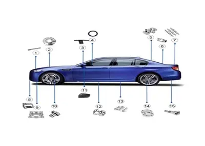 CNC Automotive Parts and Next-gen VehiclesJanuary 5, 2024Driving down the road in the not-so-distant future will be an experience unlike any other. As advances in technology continue to shape the automotive industry, one particular innovation is set to revo...view
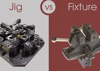 Jig vs Fixture: Understanding the Differences and Applications of Two Common Workholding DevicesDecember 1, 2023Jig vs Fixture is a common topic in manufacturing and engineering. Jigs and fixtures are two types of devices that are used to hold, support, and locate workpieces during machining or assembly processes. However, they have some differences in their design, function, and application.view
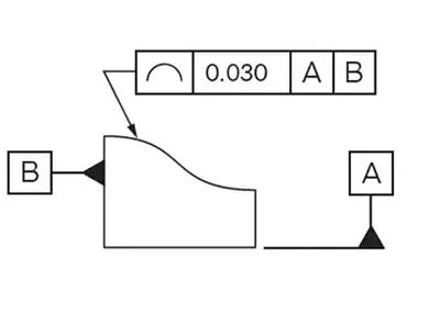 Unveiling the Precision: The Line Profile UnraveledNovember 21, 2023In the vast realm of engineering and manufacturing, the significance of line profiles cannot be overstated. These seemingly simple geometric elements play a pivotal role in ensuring precision, guiding us through the intricacies of design and production.view
 CNC Machining Technology and ProcessJuly 27, 2023CNC Machining TechnologyCNC machining technology mainly includes CNC machine tool machining technology and CNC machine tool programming technology. CNC machine tool machining technology directly compl...view
 Exploring Chameleon PVD Coating in DesignJanuary 5, 2024The world of design is constantly evolving, with new techniques and materials pushing boundaries and inspiring creativity. One such innovation that has revolutionized the design industry is Chameleon ...view
 EN
EN
 ru
ru 


