
CNC turned parts are a type of mechanical part that is manufactured through numerical control (Computer Numerical Control, CNC) technology. These parts can be used in a variety of applications, from automotive and aerospace to medical devices and industrial machinery.
CNC turned parts are mechanical parts that are manufactured using Computer Numerical Control (CNC) technology. These parts can be used in a variety of applications, from automotive and aerospace to medical equipment and industrial machinery.
CNC turned parts are parts that are manufactured by CNC lathe (Computer Numerical Control Lathe) or CNC machine tool (Computer Numerical Control Machine Tool). These parts are usually metal or plastic and have complex geometries and stringent dimensional requirements. The manufacturing process of CNC turned parts is automated, with pre-programmed computer commands controlling the movement of tools and workpieces on the lathe or machine tool in order to cut and machine raw materials with high precision.
The working principle of CNC turning involves the following key components:
Computer Control System (CNC Controller): The CNC controller is the brain of the CNC lathe or CNC machine tool, which receives commands from a pre-programmed computer program and converts them into electrical signals to control the movement of various axes and the operation of tools. This computer program includes the geometric data and machining steps of the part.
CNC Lathe or CNC Machine: This is the mechanical device that actually performs the machining. It consists of a table and tool that can be moved in multiple axes in order to cut the workpiece according to a program. CNC lathes and CNC machines can be configured to meet specific machining needs, including multi-axis control, rotary tables, and automatic tool change systems.
CUTTING TOOLS: Cutting tools are tools that are used to cut workpieces in shapes and sizes that vary depending on the requirements of the part. The tool is usually a rugged carbide that can withstand high-speed rotation and high-temperature cutting operations.
Workpiece: A workpiece is the raw material to be machined, which may be a metal bar, tube, plate or plastic. The workpiece is clamped to the table for cutting and machining.
A CNC lathe or CNC machine moves in multiple axes according to programmed instructions while rotating a tool to cut the workpiece. By controlling the movement of each axis and the position of the tool, high precision machining operations can be realized to produce parts that meet design requirements.

CNC turned parts have a wide range of applications in various fields, including but not limited to the following:
Automotive industry: CNC turned parts are used in the manufacture of automotive components, such as engines, transmissions, brake systems and suspension systems. These parts must be highly accurate and durable.
Aerospace: The aviation and aerospace industry requires high strength and lightweight parts, and CNC turning technology can meet these requirements for components used in the manufacture of airplanes, rockets and satellites.
Medical Equipment: The medical equipment industry requires precision parts for the manufacture of medical instruments and equipment such as X-ray machines, surgical tools and artificial joints.
Electronic Equipment: CNC turned parts are also used in the manufacture of electronic equipment, including cell phones, computers and communications equipment.
Energy: In the energy industry, CNC turned parts are used in the manufacture of power generation equipment, oil and gas extraction equipment and so on.
Industrial Machinery: Industrial machinery manufacturing requires a variety of parts, and CNC turning can provide efficient and consistent production. 4.
The manufacturing process of CNC turned parts usually includes the following steps:
Design: The design of the part is the first step in the manufacturing process. Design engineers use computer-aided design (CAD) software to create a geometric model of the part and dimensional specifications.
Programming: The next step in the manufacturing process is to write the CNC program. The programmer translates the design data into CNC code that includes parameters such as tool paths, cutting speeds and feed rates.
Clamping the Workpiece: The workpiece is clamped to the table on the CNC lathe or CNC machine to ensure that it is held securely in the correct position.
MACHINING: The CNC controller controls the movement of the tool according to the instructions of the program to start cutting and machining the workpiece. This includes operations such as external contour cutting, holemaking, and thread cutting.
QUALITY CONTROL: During the machining process, quality control personnel may use measuring tools to check the dimensional and geometric accuracy of parts to ensure they meet design requirements.
Deburring and Surface Preparation: Parts may require deburring or surface preparation to improve their surface quality.
Inspection and Packaging: Completed parts undergo a final inspection and are then packaged for shipment or storage.
CNC turned parts manufacturing offers several significant advantages:
High Accuracy: CNC turning can achieve very high machining accuracy, ensuring that the geometry and dimensions of the part are consistent with the design requirements.
Automation: The manufacturing process is automated, reducing the risk of human error and increasing productivity.
Complex Geometry: CNC turning allows for the manufacture of parts with complex geometries, which is critical for many applications.
Consistency: CNC manufacturing ensures that the same program can be repeated to create parts of the same quality, ensuring consistent production.
Flexibility: CNC machines can be reprogrammed as needed to produce different types of parts, increasing manufacturing flexibility.
Material Adaptability: CNC turning can be used on a wide range of materials, including metals, plastics and composites.
A lathe is a machine tool used for machining workpieces and usually consists of several parts, each with a specific function to ensure high accuracy and efficiency.
The bed is the main supporting structure of a lathe and is usually made of strong cast iron or welded construction. The main function of the bed is to provide a stable platform to support the table, spindle and other parts of the tool rest. The bed must be rigid enough to resist vibration and loads during machining.
The spindle is the core part of the lathe, which is used to rotate the tool to cut the workpiece. The spindle is usually made of high-strength alloy steel, supported by bearings and driven by an electric motor or other power source. The rotational speed of the spindle can be adjusted according to the machining requirements to control the cutting speed.
The tool post is the part that mounts and supports the cutting tool. It is usually located on the side of the spindle and can be adjusted in different angles and positions for different types of cutting operations. The tool holder usually consists of a holder, a holder chuck and a tool clamping device.
The feed system is used to control the horizontal and vertical movement of the table and tool holder for cutting and machining of the workpiece. Feed systems typically include transverse (X-axis) and longitudinal (Y-axis) feeds. These systems consist of electric motors, screws, guides, and feedback devices that precisely control the motion of the table and tool holder.
The worktable is a platform on which the workpiece is placed and which can be moved on the bed so that the workpiece can be accurately positioned and clamped. The table usually has T-slots for clamping various fixtures and workpieces. The movement of the table is controlled by a feed system to ensure that the workpiece is cut properly under the tool.
The tailstock is another important part of the lathe and is usually located at one end of the table. It is used to support long workpieces to prevent vibration and bending of the workpiece during cutting. The tailstock usually consists of a movable tailstock seat and a tailstock screw that can be adjusted to the length of the workpiece.
The lubrication system is used to keep the various parts of the lathe lubricated to minimize wear and friction and ensure smooth operation. This includes spindle bearings, feed system guides, screws and other moving parts. The lubrication system usually uses oil or grease to provide the necessary lubrication. 8.
A cooling system is used to cool the cutting area and prevent damage to tools and workpieces due to high temperatures. It also helps to remove chips and waste materials generated during the cutting process. The cooling system usually consists of a coolant tank, pumps, nozzles and coolant piping.
The electrical control system is the brain of the lathe and is responsible for controlling the various moving parts and functions of the lathe. This includes spindle speed control, motion control of the feed system, table and tool holder positioning, and various safety functions. The electrical control system usually consists of a computer numerical control (CNC) controller, electrical panels, and sensors. 10.
Lathes are usually equipped with a variety of accessory devices to enhance their functionality and to accommodate different machining needs. These include a variety of fixtures, tools, automatic tool change systems, workpiece measuring and inspection devices, etc.
To ensure operator safety, lathes are usually equipped with safety devices such as emergency stop buttons, guards, emergency stop systems and guard rails. These devices help to reduce the risk of accidents and protect the operator from potential hazards.
Control software is an important part of a CNC controller that includes pre-programmed CNC code for defining tool paths, cutting parameters, and table movement. The operator can use the control software to program and adjust the operation of the lathe to meet specific machining needs.

A CNC Turning Tool is a cutting tool for use on a CNC Lathe (Computer Numerical Control Lathe) that provides a high degree of accuracy and automation for machining a wide variety of workpieces. CNC turning tools are very different from those used on traditional manually operated lathes, and they are a key component of CNC machine operation.
1. Tool Insert: The insert of a CNC turning tool is one of its most important components. Inserts are usually made of strong carbide or ceramic materials with high hardness and wear resistance. The shape and cutting geometry of the insert can be designed according to the machining requirements, e.g. an insert for roughing may be different from an insert for fine machining.
2. Tool Holder: The insert is usually supported and secured to the CNC lathe by the tool holder. The design and material selection of the tool holder is also important because it needs to be rigid and stable enough to maintain the exact position of the insert during high-speed and high-load cutting operations.
3. Shank Attachment Components: Shanks are usually attached to the tool holder of the CNC lathe and these attachment components allow the shank to move horizontally and vertically. By adjusting these connecting parts, the feed and retract movements of the inserts can be controlled to suit different machining operations.
4. Cooling System: CNC turning tools typically have a cooling system for cooling the cutting area to prevent the workpiece and insert from overheating during the cutting process. Coolant is usually delivered to the cutting area through the toolholder and cools the workpiece and insert through cooling oil or coolant nozzles.
5. Tool holding device: This is the component used to clamp and hold the insert to ensure that the insert remains in a stable position during the cutting operation. Tool holders usually have adjustments for changing and reinstalling inserts. 6.
6. CNC System: The operation and control of CNC turning tools is usually managed by a CNC system. This system receives the machining program and controls the movement of the toolholder and cutting motion based on pre-defined cutting parameters. The CNC system can precisely control the movement of the insert to achieve high precision machining.
7. Automatic tool change systems: Some CNC lathes are equipped with automatic tool change systems, which allow changing tools without interrupting the machining process. This improves productivity, especially in cases where multiple cutting tools are required for continuous machining.
8. Tool measurement and monitoring systems: Some CNC lathes are also equipped with tool measurement and monitoring systems to detect the wear and performance of the inserts so that the tool can be changed in time and the quality of the machining can be ensured.
The main advantages of CNC turning tools are their high accuracy, automation capabilities and adaptability. They can be used to machine a wide range of workpieces in different materials, including metals, plastics, ceramics, etc., and are suitable for a variety of machining operations, such as external contour cutting, holemaking, and thread cutting. The precise control and automation features of CNC turning tools make them an indispensable tool in modern manufacturing, improving productivity and ensuring the quality of parts.
CNC (Computer Numerical Control) turning is an automated method of machining in which a computer program is used to control a lathe or machine tool cutting tool. In CNC turning, mathematical formulas and geometric parameters are used to define the shape, size and cutting path of the workpiece. These formulas and parameters are created through CAD (Computer Aided Design) software and translated into CNC code in CAM (Computer Aided Manufacturing) software so that they can be understood and executed by the CNC machine tool.
COORDINATE SYSTEM: CNC turning uses a coordinate system to describe the position and motion of the workpiece. A Cartesian coordinate system is usually used, where the X-axis represents the horizontal direction, the Y-axis the vertical direction, and the Z-axis the longitudinal direction. The origin of the coordinate system is usually at the start of the workpiece.
Points: Points are the most basic geometric elements used to define position on a workpiece. Each point consists of X, Y, and Z coordinate values.
Line: A line is used to connect two points and defines a straight path on the part. The parameters of a line include the start and end coordinates.
Arc: An arc is used to describe a curved path and consists of a center, radius, and start and end angles. These parameters define the shape and position of the arc.
Cutting Speed: Cutting speed is the linear velocity at which the tool cuts the workpiece, usually expressed in terms of distance per unit length (e.g. meters/minute or inches/minute). The choice of cutting speed depends on factors such as material type, tool material and tool diameter.
Feed Rate: Feed rate is the speed at which the workpiece moves during the cutting process and is usually also expressed in distance per unit length. The choice of feed rate affects the efficiency and quality of cutting.
Cutting depth (Cutting Depth): Cutting depth is the depth of the tool from the surface of the workpiece into the distance, usually expressed in units of length (such as millimeters or inches). The choice of depth of cut affects the cutting force and cutting temperature.
Cutting width (Cutting Width): Cutting width is the lateral movement of the tool on the workpiece, also expressed in units of length. The choice of cutting width affects the material removal rate and surface quality during the cutting process. 3.
Interpolation is a key concept in CNC turning which is used to generate tool paths to achieve complex geometries. Interpolation algorithms are based on mathematical formulas to calculate the interpolated trajectory of the tool between points to ensure smooth and continuous cutting.
Linear interpolation: Linear interpolation is the simplest form of interpolation and is used to generate straight cutting paths. The basic linear interpolation formula is a line equation that includes a start point, an end point, and a feed rate.
Circular interpolation: Circular interpolation is used to generate curved cutting paths, e.g., for chamfering and round hole machining. It calculates the path of an arc based on the arc equation and includes parameters such as the center of the circle, radius and start angle end angle.
CNC codes are sets of instructions that a CNC machine can understand and execute. These codes are represented in text form and typically include G-code and M-code. G-code is used to define cutting paths, interpolation, and coordinate systems, while M-code is used to control auxiliary functions of the machine, such as the cooling system and automatic tool change.
CNC turning programs often require the use of algorithms and mathematical libraries to perform complex mathematical operations such as interpolation, curve fitting and curve generation. These algorithms and libraries help generate accurate tool paths for high quality machining.
CNC turning is a highly precise and automated machining method that relies on mathematical formulas and geometric parameters to define the shape of the workpiece and the cutting path. These formulas and parameters are created in CAD/CAM software and translated into CNC code for precise control and efficient machining on CNC machines. Mastering these mathematical and geometric concepts is a critical skill for CNC turning operators and programmers to ensure the quality and accuracy of machined workpieces.

Calculating the cutting speed or RPM (Revolutions Per Minute) is critical in turning because it determines the speed at which the tool rotates, which directly affects the quality of the machining and tool life. Calculating RPM correctly is one of the keys to a safe and efficient machining process.
In turning processing, there is a close relationship between cutting speed (Cutting Speed, usually expressed in V) and RPM. Cutting Speed is the linear velocity of the tool when cutting the workpiece, usually expressed in meters per minute (m/min) or inches per minute (inch/min). RPM, on the other hand, is the number of revolutions per minute of the tool.
The relationship between cutting speed and RPM can be expressed by the following equation:
Cutting speed (V) = π × tool diameter (D) × RPM
According to this relationship, we can calculate the RPM, as long as we know the cutting speed and tool diameter.
The correct selection of cutting speed is very important because it affects the efficiency of machining and the surface quality of the workpiece. Cutting speed usually depends on the following factors:
Material type: different types of materials have different recommended cutting speed range. Typically, harder materials require lower cutting speeds, while softer materials can use higher cutting speeds.
Tool Material: The hardness and wear resistance of the tool material also affects the choice of cutting speed. Cemented carbide tools usually allow higher cutting speeds.
Tool Type: Different types of tools (e.g. drills, milling cutters, turning tools, etc.) have different cutting speed requirements.
Machining operations: Cutting speeds are also influenced by the specific machining operations, such as roughing and finishing, which have different speed requirements.
Cooling and Lubrication: The choice of cutting speed is also related to the lubrication and cooling system, as higher cutting speeds may require better cooling.
To calculate the RPM, you can follow the steps below:
Step 1: Obtain a value for the cutting speed. This is usually chosen based on the type of material and tool material, or you can consult a table of recommended cutting speeds.
Step 2: Determine the tool diameter (D). The tool diameter is the diameter of the cutting part of the tool, usually expressed in millimeters (mm) or inches (inch).
Step 3: Use the following formula to calculate RPM:
RPM = Cutting Speed (V) ÷ π x Tool Diameter (D)
Step 4: The calculated RPM is the revolutions per minute (RPM) you need to set the tool rotation speed on the CNC lathe.
Suppose you need to turn a piece of steel with a recommended range of cutting speed of 100 to 150 m/min and a tool diameter of 10 mm. Now, let's calculate the required RPM.
Step 1: Select the cutting speed, let's say we choose 120 m/min.
Step 2: Determine the tool diameter, in this case 10 mm.
Step 3: Calculate the RPM using the formula:
RPM = 120m/min ÷ π x 10mm ≈ 38.2rpm
Therefore, you need to set the RPM of the CNC lathe to approximately 38.2 RPM to turn at the given cutting speed and tool diameter.
There are several other precautions to consider when performing CNC turning:
Periodically check the tool for wear and damage and adjust the RPM and cutting speed accordingly.
Use proper cooling and lubrication during the cutting process to prevent overheating and wear in the cutting area.
Follow recommended ranges for cutting speed and RPM to ensure safe and efficient machining.
Depending on the specific machining task and workpiece requirements, cutting speeds and RPMs may need to be adjusted for different situations.
Calculating the RPM for CNC turning is a critical task that takes into account a number of factors such as material, tool, cutting speed and tool diameter. Calculating the RPM correctly ensures machining quality, improves tool life, and ensures safe operation. In practice, adjustments are made according to specific conditions and experience to obtain the best machining results.
A1: CNC turning is a machining process where a computer-controlled lathe is used to create parts by rotating a workpiece and cutting away excess material with a cutting tool.
A2: The key components of a lathe include the bed, spindle, tool post, feed system, worktable, tailstock, lubrication system, coolant system, electrical control system, accessories, safety devices, and control software.
A3: RPM for turning is calculated using the formula RPM = (Cutting Speed * 1000) / (π * Tool Diameter). Make sure to choose an appropriate cutting speed based on material, tooling, and operation type.
A4: CNC machining is used to create precise parts for various industries including aerospace, automotive, medical, and more. It's suitable for producing complex shapes from materials like metal, plastic, and composites.
A5: CNC turning offers advantages such as high precision, automation, the ability to handle complex geometries, consistency, flexibility, and adaptability to various materials.
 Bakelite: The First Synthetic Plastic and Its ApplicationsDecember 7, 2023Bakelite is a synthetic material that was invented in the early 20th century by Leo Baekeland, a Belgian-American chemist. Bakelite is considered to be the first true plastic, as it was the first material that was not derived from natural sources, such as cellulose, rubber, or horn.view
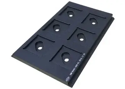 Semiconductor Chip Carrier Manufacturing: Introduction from Materials to Finished ProductsAugust 14, 2023With the development of science and technology, semiconductor chips are being widely used in various fields. High quality chip carriers are crucial to ensure the performance of chips during semiconduc...view
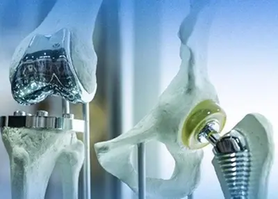 4 Surface Finishing Techniques in the Orthopedic Medical IndustryOctober 26, 2023With the development and advancement of science and technology and the innovation of mechanical parts processing technology, the society has put forward more stringent requirements for medical devices in terms of deburring and polishing surface accuracy, surface asepticization, and compatibility with implanted materials.view
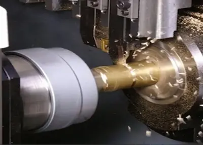 5-Axis CNC Machining: Faster Speeds and Higher PrecisionJuly 27, 2023One of the ambitious goals of the manufacturing industry is to complete processing in one go: putting a piece of material into a machine tool, running a program, and finally obtaining a perfectly Mach...view
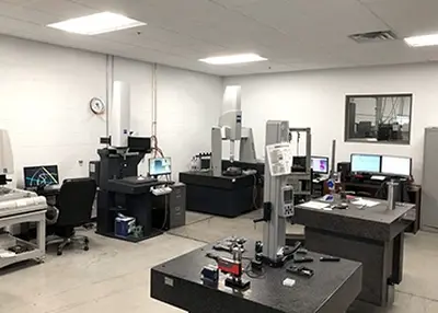 Aero-engine Why the Whole Leaf DiskOctober 23, 2023Aero-engine is the heart of the aircraft, also known as the pearl in the crown of industry, the manufacture of which integrates a lot of cutting-edge technology in modern industry, involving materials, machining, thermodynamics and other fields.view
 The Functional Advantages of Custom PVD Coating in Automotive DesignJanuary 5, 2024When it comes to automotive design, every detail matters. From the sleek lines of the exterior to the carefully crafted interior, each element plays a crucial role in creating a unique and memorable d...view
 EN
EN
 ru
ru 


