In the physical world, the sharp edges of 3D models may not be visually appealing or practical. Experts suggest that chamfered edges offer a more aesthetically pleasing appearance, while also improving the usability and safety of parts and products.
When machining metal parts, it is common for the edges to be sharper than desired for end-users. To address this, designs often incorporate chamfers to smooth or break those sharp edges. This article comprehensively explains the concept of chamfer, covering its types, advantages, limitations, when and how to use them, and methods for creating chamfered edges. By delving into these topics, you will gain a thorough understanding of chamfers and their significance in engineering and design.

Chamfer, a term widely used in both CAD and engineering, refers to the process of creating an angled or beveled edge. In CAD, chamfering edge is a common technique used to smooth and enhance the safety of model edges. In engineering, chamfering is applied to facilitate assembly, reduce stress concentrations, and improve the overall safety and functionality of parts and components.
In CAD, a chamfer definition can be created using the built-in "CHAMFER" command. To apply a chamfer, simply type "CHAMFER" in the command line and select the two lines that you want to connect with the chamfer. You can then specify the length of the flat face section or the desired angles for the chamfer. Once the parameters are set, CAD will automatically remove the sharp edge and generate the chamfer according to your specifications. This feature in CAD simplifies the process of creating chamfers, allowing for precise and efficient design modifications.
I understand that you already know what is a chamfered edge, but what does chamfer mean in engineering? In engineering, a chamfer is used to remove the sharp edges of a hole or other feature. It can also be used to create an angled edge on metal parts and components. The chamfer's angle depends on its purpose, with the most common angles being 45° and 60°. When creating a chamfer in engineering, a chamfering tool is used to cut the angled edge.

Chamfering holes are a common practice in engineering where an angled or beveled edge is applied to a hole to facilitate the insertion of assembly components like bushings, pins, or screws. This process prevents interference during insertion and ensures a smooth fit. It is especially important for threaded holes as chamfering prevents the development of raised burrs that could damage the threads. By removing any sharp edges or burrs, chamfering promotes the longevity and functionality of the final product by preventing thread damage and facilitating hassle-free assembly.
When we define chamfering, the most common method is to provide the leg length size and the chamfer angle. The leg length refers to the sizes of the two sides of the triangle that form the chamfer. Typically, the legs are represented by the sides "a" and "b" of the triangle. The chamfer angle indicates the inclination or slope of the chamfer.
In cases where the meaning of chamfered angle is not explicitly stated, define chamfered to be 45 degrees. However, this assumption can be risky as it may not align with the intended design or functional requirements. Confirming the chamfer angle when it is not directly specified is always recommended, to ensure accurate and safe implementation.
By providing both the leg length and chamfer angle, precise specifications can be given for chamfers, allowing for proper interpretation and execution in manufacturing or design processes.
In some cases, chamfer define as measured as a face width, indicated by the abbreviation F.W. on blueprints.
To clarify, when measuring a chamfer as a face width, the leg length of the chamfer refers to the lengths of the "a" and "b" sides in the picture. In a 45-degree chamfer, these leg lengths will be equal. The length of the "c" side represents the face width of the chamfer and is measured along the hypotenuse.
Converting between leg length and face width can be done by multiplying the leg length value by 1.414 to obtain the face width. Conversely, to convert from face width to leg length, divide by 1.414. However, it is important to note that these conversion factors are applicable only for chamfers at a 45-degree angle, which is the most common chamfer angle. For chamfers at different angles, a triangle calculator or specific trigonometric calculations may be required.
What are chamfers? Chamfered edges, also known as beveled edges, offer several advantages across different applications. Some key advantages of chamfered edges include:
1. Improved Safety
Chamfering removes sharp corners and edges, reducing the risk of injuries caused by accidental bumps or collisions. This is particularly important for objects that come into contact with people, such as furniture, countertops, and children's toys.
2. Enhanced Durability
Chamferred edges help distribute stress and impact forces more evenly along the edge. By reducing stress concentrations at sharp corners, chamfer edges can increase the overall durability of an object, making it less prone to cracking or chipping.
3. Aesthetic Appeal
Chamfered edges can add visual interest and elegance to various objects and architectural elements. The beveled profile breaks up sharp angles, creating a more refined and visually pleasing appearance. This aesthetic advantage is commonly utilized in furniture design, decorative moldings, and even electronic devices.
4. Easy Assembly
Chamfered edges can facilitate the assembly of components by providing a guide for alignment. When two chamfered edges come together, they can easily slide into position, ensuring a precise fit. This advantage is particularly useful in woodworking, metalworking, and construction industries where precise fitting is crucial.
5. Smoother Transitions
Chamfered edges create smoother transitions between different surfaces or materials. Instead of abrupt changes or sharp angles, chamfer the edges to provide a gradual slope or beveled profile. This adds visual appeal and helps create seamless transitions. In carpentry, cabinetry, or architectural applications, chamfered edges are often used to achieve smooth and harmonious transitions between different elements.
While chamfered edges offer numerous advantages, there are specific instances where creating them may not be appropriate. Here are some scenarios where chamfered edges may not be suitable:
1. Structural Integrity
Highly important when maintaining the overall stability and strength of an object. In situations where sharp edges provide crucial support or rigidity, chamfering them may compromise the structural considerations.
2. Design Intent
In some design styles or aesthetic concepts, the inclusion of sharp corners or edges is deliberate for visual impact or to convey specific themes. Chamfering these edges would deviate from the intended design requirements, potentially undermining the desired artistic expression.
3. Functional Requirements
Applications that necessitate efficient gripping surfaces or precise mechanical interfaces may rely on sharp edges to ensure optimal functionality. Chamfered edges in such cases may reduce necessary friction or contact area, thereby impairing the intended functionality.
4. Material Compatibility
Certain materials, particularly those that are brittle or fragile, may not be suitable for chamfering. The process of chamfering can weaken such materials or escalate the risk of cracks and breakages. Thus, careful consideration of material limitations is essential.
5. Constraints of Time and Cost
In scenarios where time and cost are significant considerations, the inclusion of chamfered edges may incur additional expenses or prolong the manufacturing process. It may be more practical to opt for simpler edge treatments to meet constraints without compromising the quality of the workpiece.
Chamfered edges find application in various domains of manufacturing physical products. Some of the key manufacturing processes where chamfered edges are commonly utilized include:
1. Carpentry
In carpentry, chamfered edges are often created on wood pieces to add a decorative touch or to facilitate smooth transitions between different components. Chamfers on furniture edges, moldings, or trim pieces can enhance the visual appeal of the finished product.
2. Metalworking
Chamfered edges are frequently used in metalworking processes such as welding or fabrication. Chamfering metal edges helps to remove any burrs or sharp edges left from the machining or cutting process. This not only enhances the safety of the metal components but also improves the overall aesthetic quality.
3. Machining
Chamfering is an essential machining process used in industries such as automotive, aerospace, and general manufacturing. It involves creating beveled edges on metal or plastic components to facilitate easy assembly, prevent stress concentrations, and enhance the overall functionality and durability of the finished products.
To create a corner chamfer in CAD with the same distance on both edges, follow these steps:
Step 1. Select the "Corner Chamfer" command from the "Modify" panel under the "Sheet Metal" tab.
Step 2. Choose the "One Distance" option.
Step 3. Select the corners on the model edges that you want to chamfer. You can choose a single corner or multiple corners.
Step 4. In the "Distance" drop-down list, specify the desired chamfer distance.
By opting for the "One Distance" option, you can achieve consistent offset distances from the corners on both sheet metal edges. This feature allows for precise and uniform chamfering.
To create a corner chamfer in CAD with a specified distance and angle, you can follow these steps:
Step 1. Select the "Corner Chamfer" command from the "Modify" panel under the "Sheet Metal" tab.
Step 2. Choose the "Distance and Angle" option.
Step 3. Click on the sheet metal edge from which the chamfer will be angled.
Step 4. Click on one or both corners of the sheet metal edge to apply the chamfer. Note that you can select only sheet metal edges and model edges that represent corners.
Step 5. In the "Distance" and "Angle" drop-down lists, specify the desired chamfer distance and angle.
Distance: This determines the offset distance from the selected sheet metal edge for chamfers defined by one distance or by a distance and angle.
Angle: This specifies the angle applied to chamfers defined by a distance and angle.
To create a corner chamfer in CAD by specifying a distance for each edge, you can use the "Two Distances" option. Here's a simplified explanation:
Step 1. Click on the "Corner Chamfer" command in the "Modify" panel under the "Sheet Metal" tab.
Step 2. Select the "Two Distances" option.
Step 3. Click on the corner that you want to chamfer. This should be a model edge that represents a corner.
Step 4. Enter the values for "Distance 1" and "Distance 2":
Distance 1: It specifies the first offset distance for chamfers defined by two distances.
Distance 2: It specifies the second offset distance for chamfers defined by two distances.
Step 5. Click on "Flip" to reverse the direction of the chamfer distances, if needed.

Bevel: A bevel is a plane on the part that is inclined at any angle to the reference plane. It involves creating a sloped surface or edge that deviates from the original reference plane. Bevels can be applied to various surfaces or edges of a workpiece.
Chamfer: Chamfering, on the other hand, refers specifically to the machining process of cutting the edges and corners of the workpiece to create a certain slope. It involves removing material from the sharp edges, resulting in a beveled or angled transition between the adjacent surfaces.
Bevel Tool: The bevel tool is designed to create beveled edges or inclined planes on a workpiece. It is used to shape or angle the edges to a specific degree relative to the reference plane. The bevel tool can either be manual or powered, depending on the application and requirements.
Chamfer Tool: The chamfer tool is specifically designed to create chamfered edges. It is used to remove material from the edges and corners of the workpiece to create a beveled or angled transition between surfaces. The chamfer tool can come in various forms, including hand tools, power tools, or dedicated machining tools, depending on the complexity and precision required.
Bevel: The inside shape of a bevel, formed by the inclined plane, will typically be a rhombus. A rhombus is a parallelogram with opposite equal acute angles.
Chamfer: The inside shape resulting from a chamfer will generally be an octagon. An octagon is a polygon with eight sides and eight angles.
Beveling: Beveling does not necessarily imply cutting. While beveling often involves the removal of material to create an inclined plane or edge, it can also refer to the process of shaping or angling existing surfaces without cutting. Beveling can be achieved through various methods such as grinding, sanding, or even molding, depending on the specific application and desired outcome.
Chamfering: On the other hand, chamfering specifically refers to cutting or machining. It involves removing material from the edges or corners of a workpiece to create a beveled or angled transition. Chamfering is typically performed using tools like chamfer mills, routers, or specific machining techniques, resulting in a precise and defined slope.
Chamfers and break edges are both methods used to remove sharp edges from parts, but they have some key differences:
Chamfer
Chamfers are often added as an additional feature on a blueprint. They may not have a specific functional requirement but are included to protect the part and individuals who may come into contact with it. Chamfers are typically specified with a specific size and angle and are controlled more precisely. The angle and dimensions of the chamfer are typically defined on the blueprint.
Break Edge
A break edge, on the other hand, is a more general requirement to remove the sharp edge from a part. It is often specified when the requirements are not as strict, and there may not be a need for specific size or angle control. Break edge callouts will typically not be identified with a specific angle associated with them. The size of the break edge is usually specified as a range (e.g., .010″-.020″) or sometimes even less.
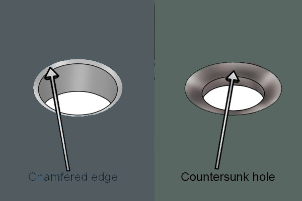
Chamfers and countersinks are both features used to remove sharp edges, but they have distinct characteristics:
Chamfer
A chamfer is an angled surface or edge formed by cutting or grinding material. It is typically specified at a 45-degree angle, although other angles can be used as well. Chamfers are commonly applied to straight edges, such as the corners of a part, and are often used for aesthetic or safety reasons.
Countersink
A countersink, on the other hand, is a chamfer applied specifically to a round feature, such as a hole or recess. It is designed to allow a screw or bolt to sit flush with or below the surface of the material when tightened. Countersinks have a wider range of common angles compared to chamfers, with typical angles being 82, 90, 100, and 120 degrees.
One key difference between chamfers and countersinks is how the angles are specified. Chamfers are usually designated by their angle, such as 45 degrees, while countersinks are specified as the angle between two opposite sides of the feature. This results in the angle specification for a chamfer being doubled for a countersink. For example, a 45-degree chamfer would often be listed as a 90-degree countersink.
While chamfer and deburr, both involve removing sharp edges, there are some distinctions between them:
Chamfer
Chamfered meaning is an angled cut or surface that is applied to the edges or corners of a part. It is typically specified with a specific size and angle, and it serves various purposes like enhancing aesthetics, reducing stress concentrations, or facilitating assembly. Chamfers are more controlled and defined, often specified with precise dimensions and angles.
Deburr
Deburring, on the other hand, focuses on removing or smoothing sharp edges and burrs that can be left after manufacturing processes such as cutting, drilling, or machining. It aims to eliminate any rough or uneven edges to prevent injuries and improve the overall quality of the part. Deburring often involves using specialized tools or techniques to remove raised edges or undesired metal burrs from the workpiece.
In terms of callouts, chamfer specifications are typically more precise, while deburr callouts tend to be less strict and allow more flexibility. Deburr callouts are generally looser in nature and do not typically provide specific dimensions or angles, allowing for more subjective interpretation by the operator or finishing processes.
1. Determine the Reference Plane
Identify the two intersecting surfaces about what is a chamfer edge
2. Use a Protractor
If the chamfered definition is clear and accessible, you can use a protractor to directly measure the angle. Place the base of the protractor on one of the surfaces or edges and align the zero-degree mark with the reference plane. Then, read the angle indicated by the protractor.
3. Use a Triangle Calculator
If the chamfer is not easily accessible or cannot be measured directly, you can use a triangle calculator or trigonometric calculations. Measure the leg lengths of the chamfer and input them into the appropriate fields of the triangle calculator. It will calculate the angles of the triangle, including the chamfer angle.
4. Confirm with the Chamfer End Mill
In some cases, the chamfer angle may be assumed to be the same as the tool used to generate it. If a specific tool was used to create the chamfer, refer to the specifications of that tool to determine the expected angle. However, note that this assumption may not always hold true, as chamfers can be manually created or generated using various methods.
By using a protractor, triangle calculator, or referring to tool specifications, you can accurately measure the angle of what is a chamfer. This information is essential for both manufacturing and design purposes to ensure the proper execution
Conclusion
Understanding the concept of chamfers should not be confusing. Chamfers can be a valuable addition to your design, but selecting the appropriate type is crucial for optimal results in part design. Making the right choice can lead to improved efficiency, cost savings, and increased longevity.
However, instead of struggling with the design process, why not consider outsourcing to professional companies that specialize in this field? At Richconn, we are here to assist you with our extensive expertise in design engineering and part manufacturing. We guarantee that our designs will excel during the manufacturing stage.
If you already have a design in mind, there's no need to worry. We also provide professional tips and suggestions to further enhance your design.
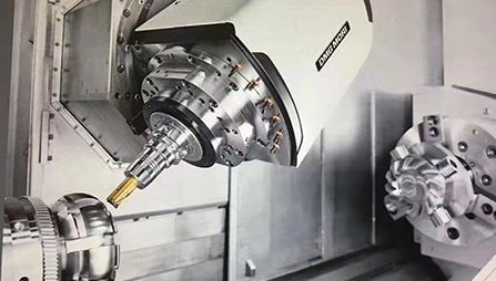
When it comes to cutting and milling your design, we offer a seamless process. With our 3, 4, and 5-axis milling capabilities, we ensure successful CNC machining projects. Additionally, we conduct rigorous quality inspections and provide material certifications to certify the superior quality of our parts. All of these services are offered at competitive industry prices.
Choose Richconn for your design and manufacturing needs, and experience the convenience, expertise, and affordability that we bring to every project.
 Safety Issues in CNC Turning TechnologyApril 25, 2023Turning is a part of mechanical processing in lathe machining. Lathe machining mainly uses the turning tool to process the rotating workpiece. Lathes are mainly used to process shafts, discs, sleeves,...view
 Super-material carbon fiber: raw material production and its application and processingDecember 20, 2023Carbon fiber materials are used more and more widely, and their manufacturing is correspondingly accepted by more people. Price, capability and quality are all our advantages.view
 Unveiling the Precision World of Machined Gears: A Richconn PerspectiveNovember 10, 2023In the intricate tapestry of mechanical engineering, machined gears stand as the unsung heroes, translating rotational motion with unparalleled precision. These gears are meticulously crafted to meet the demanding requirements of various industries, ensuring seamless operation in complex machinery.view
 304 vs 316 Stainless Steel: Which Is the Right Grade for Your Project?August 24, 2023The comparison between 304 and 316 stainless steel is always the key problem when choosing the right stainless steel grade for your project. Both of these grades belong to the austenitic stainless ste...view
 How to Get a Clear Picture of Quenching, Normalizing, Tempering and Other Material Heat Treatment Issues?October 24, 2023Heat treatment of steel consists of normalizing, annealing, tempering and quenching. Among them, annealing and normalizing are mainly used for preparatory heat treatment, and are only used as final heat treatment when the performance of the workpiece is not required. The purpose of quenching is to obtain martensitic organization and improve the performance of steel.view
 How Much Does Injection Molding Cost?August 9, 2023Injection molding is a widely used manufacturing process for the production of components and products. As with any manufacturing process, it is crucial to understand the cost factors involved in inje...view