
* Tolerances are important when designing assemblies, but should be chosen wisely.
* Generally, the lower the tolerances, the more the cost of manufacturing, measurement and quality assurance increases.
* Keep it simple to save time and money. For most components, a tolerance of ±0.1 mm is sufficient.
* Create prototypes to test what tolerances are needed.
* Use dimensionally stable materials when holding tight tolerances is important.
Tolerances that are too tight can require rework, which in turn drives up costs. If tolerances are too loose, the part may not fit with the mating part. So to optimize your designs, know what tolerances are needed and when: Standard tolerances can improve quality, ensure fast repeatability and reduce manufacturing costs.
Dimensional tolerances and the interchangeability of components are part of the common concept of modern manufacturing. The advantage of producing "identical parts" to fit any assembly of the same type has been known since 1841. In that year, Sir Joseph Whitworth introduced the British Standard Whitworth (BSW) thread, still named after him today, which represented a tremendous advance for distributed manufacturing. It allowed both competition and cooperation between different manufacturers.

At Richconn, our standard prototype and production machining tolerances are +/- 0.005 inches (0.13 mm). But if you need more accuracy, our standard accuracy or production machining tolerance is +/-0.002 inches (0.051 mm). We are also able to maintain +/- 0.0002 in. (0.00508 mm) on reamed holes and +/- 0.002 in. (0.051 mm) on feature locations, provided those features are machined on the same side of the part.
It's easy to add tight tolerances at the design and prototyping stage and use form and position tolerances to build too many constraints into the design. This will inevitably drive up manufacturing costs and limit sourcing options later in the development cycle. The strictest tolerances may require additional machining steps such as grinding, polishing or electrical discharge machining (EDM), which increases both cost and, more importantly, lead time.
On the other hand, if tolerances are too loose, parts may be difficult or impossible to assemble.
To give you an overview of possible tolerances and associated costs, in this article we explain what tolerances are generally available at Richconn and which of them are common. Finally, we look at Geometric Dimensioning and Tolerancing (GD&T) tolerances, which are defined under BS 8888:2020, ISO and ASME.
Many suppliers still require a 2D drawing. This allows, for example, surcharges to be calculated for the tight tolerances, while costs are saved on the rest of the component due to larger general tolerances. Richconn uses a moderate standard tolerance of ±0.1 mm for manufacturing. This simplifies design and saves time in drawing creation and communication. For most parts, this tolerance is sufficient: 54% of functional parts can be manufactured with a tolerance of ±0.1 mm or less.*According to research by Protolabs
A design can be unnecessarily constrained in two ways: either by adding excessively tight tolerances or by restricting a degree of freedom more than once - for example, by having one pin restrict movement on the x- and y-axes and a second pin prevent rotation. Excessive constraints also add cost to grooves and inserts.
Richconn offers surface quality with an average roughness Ra of 1.6 µm as standard for its entire range of CNC materials. Center roughness Ra values between 6.3 µm and 0.8 µm are generally the norm for CNC machining. Optional bead blasting can be used to achieve a slightly rougher, but more uniform, matte surface. For detailed illustrations, refer to the CNC Surface Treatment Guide.
Adjusting the design can result in an accurate fit and ensure the feasibility of your part. However, you can also test the required tolerances:
* Shim: The height or clearance can be adjusted with a shim or washer.
* Set screw: set screws or fine-thread screws can be used to change the position of components or to press a component against a stop. It is important to consider how the component will later be fixed in this position (locknut, thread lock or screw).
* Press fit: Two components can be pressed to a known height or position.
* Shrink fit: By heating a component (i.e. thermal expansion), two components can be joined together for a precise fit.
These processes are all excellent for fixtures, test stands, and assembly tools.
Fine-tunng tolerance dimensions in your designs for CNC machining parts can help maximize those parts' quality and reduce cost.

Fine-tuning tolerance dimensions in the design of CNC machined parts can help maximize the quality of those parts and reduce costs.
If your part is intended for mass production, you should definitely avoid manual finishing steps such as deburring and polishing. These are highly dependent on technical expertise and lead to deviations. In the test and prototype phase, on the other hand, you can quickly adjust the tolerances of your design by grinding, polishing and using a quick measurement process. Another option is to create multiple designs for assembly testing. CNC machining and 3D printed parts can be used to quickly create a test series.
What is a "Mü"?
An "Mü" or micrometer (µm) is a thousandth of a millimeter - and invisible to the naked eye: a smoke particle from a cigarette, for example, has a diameter of 1 µm. When you hold your smartphone in your hand, it can expand by up to 68 µm due to the heat of your hand - just to put our standard tolerance of ±100 µm into perspective. However, you should only measure in microns if you plan to normalize for 24 hours and take the measurement in a temperature-controlled environment with a coordinate measuring machine (CMM) (Richconn offers this).
(# Aluminum alloy CTE = 24 µm/m/°C, ambient temperature: 18 °C, case temperature: 37 °C, smartphone length: 150 mm).
On request, we measure your parts by means of coordinate measuring machine (CMM), laser scanner or other measuring techniques. In addition, we go through the production part acceptance process (PPAP) with you, issue a COC certificate according to your specifications, and provide first article inspection reports (FAIs) and technical data sheets on the materials used.
"Although Richconn had specified a tolerance of ±0.1 for the aluminum parts in the quotation, all dimensions were within ±0.05 mm" - customer comment.
In order to meet the specified tolerances, Richconn uses feasibility studies. As a result, we often exceed the tolerances specified in the quotation because different machine settings and material types are taken into account. To determine the best tolerances:
* Align all dimensions to be machined that are related to each other in the same plane, if possible (so they can be machined with the same setting).
* Use materials with a low Coefficient of Thermal Expansion (CTE).
* Use plastics with good hygroscopic properties: Water absorption changes the size and shape, which affects CNC machining of glass-filled plastics.
At Richconn, we offer both a fully automated machining option for fast turnaround or a high-precision option with extended milling and post-machining capabilities for the highest complexity parts. Whether Prototype Manufacturing or production parts, we have all of your CNC milling and CNC turning needs covered.
Shape and position tolerances (GD&T) provide designers with the ability to identify priority manufacturing criteria through drawing entries for manufacturers. For example, they can use the form and position tolerances to request a special manufacturing sequence or even a different manufacturing process. Since this includes fits between different part features, it also requires more quality control, measurement, and testing.
Limits and fits: These are indicated (according to ISO 286-2) per bore with a letter and a number - along with the general bore diameter. An uppercase letter is used for bores (e.g. H7) and a lowercase letter for shafts (e.g. g6). The larger the number, the higher the tolerance:
* 9 and higher is generally used for milling and drilling.
* 7 is generally used for reaming bores: Here, a separate reamer is required for each bore size.
* 6 and lower require even more accurate machining.
The letter indicates the deviation from the nominal value, where the nominal value is indicated by "H". K and higher are above the nominal value (interference fit). G and lower are below the set point (clearance fit).
The GD&T system is good for indicating how each of the different tolerance classes (Mitutoyo, ImechE or NPL) should be used and measured. How do form and position tolerances affect manufacturing?
Nominal Position: This is usually indicated with a diameter symbol to represent the tolerance applied in all directions. It is an absolute value, i.e., 0.030 means ±0.015. Bores almost always need to be reamed because an irregular bore diameter will affect form and position tolerance. Calibrated CNC equipment and meticulous gauge adjustments are required.
Flatness: Milled surfaces are usually relatively flat. Adding very close flatness is usually a criterion for surface grinding. Adding parallelism means that two surfaces must be perpendicular to each other. Surface finishing is often required here (to achieve the measurement tolerance). Tip: Slightly raised supports or marks on the drawing showing only the areas where flatness is critical can simplify fabrication and measurement.
Cylindricity, concentricity and unbalance: For bores and shafts, unbalance is most commonly indicated because it is easier to measure, using a dial test indicator (DTI) to determine the deflection of the rotating workpiece. Since it is a complex measurement, further measurements may be required to determine if it is cylindrical (not ovoid) or concentric (off center of rotation).
Rectangularity (squareness): CNC milling machines are calibrated to verify that the tools are perpendicular to the machining bed, which ensures good squareness, especially over short distances. The tighter the perpendicularity tolerances, the more costly and time-consuming it is to produce.
Summary: It is important to know the tolerances and the GD&T system and to apply both properly. Inserting the tolerances into your CAD model is quick. However, always check to see if the constraints are really necessary, as they sometimes lead to unnecessary rework and therefore unnecessary costs. Take advantage of our fast quoting and manufacturing based on your CAD models. After all, a physical part still offers the best opportunity to test the functionality and fit of a design.
Let us help you with your projects. Just give us a call or send us an e-mail. We will be happy to advise you. You can always reach our application engineers at sales@richconn.com.cn or by phone at +86-0755-28025755. Ready for your next project? Simply upload your CAD file via our website.
 How Much Does Injection Molding Cost?August 9, 2023Injection molding is a widely used manufacturing process for the production of components and products. As with any manufacturing process, it is crucial to understand the cost factors involved in inje...view
 Extrusion Blow Molding: A Guide to the Process, Materials, and ApplicationsDecember 5, 2023Extrusion blow molding is a process of forming hollow plastic parts by extruding a molten tube of polymer and inflating it with air inside a mold. It is one of the most common and versatile methods of producing plastic containers, such as bottles, jars, jugs, and drums.view
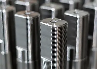 Some Knowledge You Need to Learn About Tapped HoleNovember 16, 2023Do you need taped holes? This article covers the factors you must consider to manufacture the tapped hole during the process.view
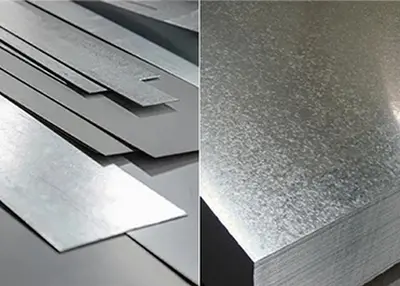 Unveiling the Power of Galvanized Materials: Your Ultimate GuideSeptember 28, 2023Have you ever wondered about the remarkable process that transforms ordinary steel into a corrosion-resistant wonder material? Look no further, as we embark on an enlightening journey to understand the world of galvanization.view
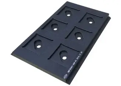 Semiconductor Chip Carrier Manufacturing: Introduction from Materials to Finished ProductsAugust 14, 2023With the development of science and technology, semiconductor chips are being widely used in various fields. High quality chip carriers are crucial to ensure the performance of chips during semiconduc...view
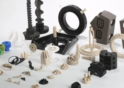
 Unveiling the World of Complex Machined Parts: A Comprehensive ExplorationNovember 14, 2023Embark on a journey into the intricate realm of complex machined parts, where precision meets innovation and engineering excellence takes center stage. In this comprehensive exploration, we'll delve into the definition, manufacturing processes, applications across industries, quality standards, material selection, market trends, and even the key players in the supply chain. Get ready to unlock the secrets behind these components that power the machinery shaping our modern world.view
 EN
EN
 ru
ru 
")

