In the vast realm of engineering and manufacturing, the significance of line profiles cannot be overstated. These seemingly simple geometric elements play a pivotal role in ensuring precision, guiding us through the intricacies of design and production. Join me on this exploration as we delve into the world of line profiles, uncovering their nuances, applications, and the critical role they play in the realm of Geometric Dimensioning and Tolerancing (GD&T).
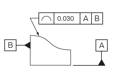
A line profile, at its core, embodies more than a mere line on a blueprint; it encapsulates the essence of form, function, and geometric intricacies. It delineates not just the shape of an object but also the critical parameters defining its integrity and functionality. From straight lines to complex curves, understanding the anatomy of a line profile is essential for engineers striving for absolute precision in their designs.
Table 1: Sample Line Profile Characteristics
| Type of Line Profile | Characteristics |
|---|---|
| Straight Line | Unidirectional, linear, constant curvature |
| Curved Line | Variable curvature, complex trajectory |
| Angled Line | Diagonal orientation, varied intersections |
Geometric Dimensioning and Tolerancing (GD&T) emerges as a pivotal framework, elevating the role of line profiles in engineering blueprints. Through the lens of GD&T, line profiles transcend their static representation, becoming dynamic elements crucial for communicating design intent and tolerances with absolute clarity.
Table 2: GD&T Symbols for Line Profiles
| Symbol | Definition |
|---|---|
| ⌓ | Defines a line profile within specified limits |
| ↳ | Indicates a profile tolerance zone |
| ⊕ | Represents the datum reference for the profile |
The transition from 2D blueprints to 3D designs amplifies the importance of line profiles, demanding a nuanced understanding of their behavior in three-dimensional space. Here, engineers encounter challenges in defining profiles that transcend multiple planes, ensuring seamless integration and functionality in complex structures.
Table 3: 3D Line Profile Considerations
| Challenge | Solution |
|---|---|
| Intersection of Profiles | Use sectional views for clarity |
| Three-dimensional Curves | Employ software for precise modeling and visualization |
| Profile Alignment | Utilize reference features for accurate positioning |
The journey of a line profile doesn't culminate on the drawing board; it extends into the manufacturing domain, where precision is transformed from concept to reality. Engineers navigate the challenges of translating design specifications into tangible products, leveraging line profiles as guiding principles for manufacturing excellence.
Table 4: Line Profile Manufacturing Parameters
| Manufacturing Process | Impact on Line Profile Precision |
|---|---|
| CNC Machining | Tool accuracy, cutting speeds, surface finishes |
| 3D Printing | Layer adhesion, nozzle precision, material flow |
| Injection Molding | Mold design, material flow, cooling rates |
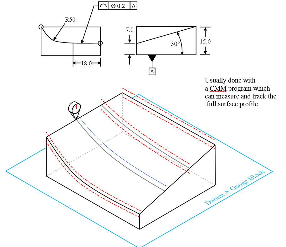
Line profiles, diverse in their forms, possess distinctive characteristics that shape the functionality and behavior of engineered components. Straight lines exhibit uniformity and simplicity, while curved lines introduce complexity with their varying curvatures and trajectories. Angled lines, on the other hand, offer a blend of directionality and intersections, influencing the spatial orientation of structures and components.
Delving Deeper: Complexities within Line Profiles
Within the realm of line profiles, complexities abound. Understanding the intricacies of curved lines involves deciphering the nuances of variable curvature, which can dictate the performance of components in dynamic systems. Angled lines, through their varied intersections, often pose challenges in alignment and integration, necessitating meticulous attention to detail in design and manufacturing.
GD&T emerges as a beacon of precision in the domain of line profiles. Symbols such as ⌓, ↳, and ⊕ in GD&T blueprints serve as powerful communicators, defining the boundaries, tolerances, and reference points for line profiles. These symbols transcend mere representation, becoming the language that engineers employ to communicate intricate design specifications with unwavering accuracy.
Elevating Understanding: Interpretation of GD&T Symbols
The interpretation of GD&T symbols requires a keen eye and a comprehensive understanding. ⌓ encapsulates the permissible deviation of a line profile within specified limits, while ↳ defines the tolerance zone within which the profile must reside. ⊕, as a datum reference, serves as the anchor point for the profile's measurement and alignment, ensuring adherence to design intent.
The transition from two dimensions to three-dimensional design introduces a new dimension of challenges regarding line profiles. Curves extend beyond the plane, requiring engineers to visualize and define profiles in a volumetric space. Addressing these challenges involves employing sectional views for clarity, utilizing software for precise modeling, and leveraging reference features for accurate positioning.
Visualizing Precision: Tools for 3D Line Profile Modeling
Cutting-edge software enables engineers to navigate the complexities of 3D line profiles. Visualization tools aid in accurately representing the behavior of line profiles across multiple planes, ensuring seamless integration and functionality within complex structures. Engineers harness these tools to visualize and manipulate line profiles in a three-dimensional space, refining designs with unparalleled precision.
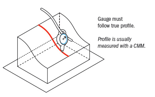
As engineering transitions into the realm of three dimensions, the intricacies of line profiles extend beyond mere visual representation. The challenges encompass defining and manipulating line profiles across multiple planes and perspectives. Engineers grapple with the complexities of accurately portraying and understanding the behavior of line profiles in volumetric space, ensuring seamless integration within complex structures.
Overcoming Obstacles: Solutions for 3D Line Profile Modeling
In the face of these challenges, cutting-edge software tools emerge as beacons of precision. Engineers employ these tools to visualize, manipulate, and analyze line profiles in three-dimensional space. Sectional views aid in comprehending the behavior of line profiles across different axes, facilitating the creation of designs that seamlessly traverse the boundaries of three dimensions.
Transitioning from the drawing board to the manufacturing floor marks a pivotal phase in the journey of line profiles. Precision in design finds manifestation in the manufacturing process, where engineers translate blueprints into tangible components. Every aspect of the manufacturing process, from machining to 3D printing and injection molding, bears an impact on the fidelity of line profiles and, consequently, the quality of the final product.
Precision in Practice: Parameters Affecting Line Profiles in Manufacturing
Machining processes rely on tool accuracy, cutting speeds, and surface finishes to maintain the fidelity of line profiles. In 3D printing, considerations revolve around layer adhesion, nozzle precision, and material flow, all of which influence the accuracy of line profiles in printed structures. Injection molding involves intricate mold designs, material flow dynamics, and cooling rates, each influencing the integrity of line profiles in molded components.
Drawing distinctions between line profiles and surface profiles reveals their unique attributes and applications. While line profiles focus on defining features along a linear path, surface profiles encompass broader areas, encapsulating multiple points within a specified boundary. The comparison highlights the precision of line profiles in guiding the creation of specific features compared to the comprehensive coverage offered by surface profiles.
Optimal Application: Choosing Between Line and Surface Profiles
Understanding the nuances between line and surface profiles enables engineers to make informed decisions. Line profiles excel in defining singular features with precision, ideal for components where specific paths or edges hold paramount importance. On the contrary, surface profiles offer a holistic view, suitable for encapsulating broader areas or complete surfaces within defined boundaries.
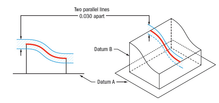
Line profiles and surface profiles delineate distinct dimensions within engineering blueprints. Line profiles concentrate on defining features along a linear trajectory, offering precise specifications for individual elements. In contrast, surface profiles encompass broader areas, encapsulating multiple points within a specified boundary. This distinction is pivotal in guiding engineers in choosing the appropriate representation for their designs, considering the granularity and scope required.
Practical Applications: Optimizing Line and Surface Profiles
Understanding the practical implications of line and surface profiles aids engineers in their application. Line profiles excel in defining singular features with meticulous precision, ideal for components where specific paths or edges hold paramount importance. Conversely, surface profiles offer a comprehensive view, suitable for encapsulating broader areas or complete surfaces within defined boundaries, providing a holistic representation for larger structures or inclusive features.
Geometric Dimensioning and Tolerancing (GD&T) serves as the bedrock for communicating intricate design specifications related to line profiles. Symbols such as ⌓, ↳, and ⊕ act as powerful communicators, defining boundaries, tolerances, and reference points for line profiles. These symbols transcend mere representation, becoming the language through which engineers communicate complex geometric parameters with utmost precision, ensuring adherence to design intent across manufacturing processes.
Harnessing GD&T: Optimizing Line Profile Tolerances
The strategic application of GD&T in defining line profile tolerances is a cornerstone in engineering blueprints. ⌓ encapsulates the permissible deviation of a line profile within specified limits, while ↳ defines the tolerance zone, ensuring the profile resides within defined boundaries. ⊕, serving as a datum reference, anchors the measurement and alignment, ensuring conformity to design specifications and maintaining precision in manufacturing.
Transitioning from blueprints to the manufacturing floor, line profiles play a crucial role in guiding precision. Every aspect of the manufacturing process, from machining to 3D printing and injection molding, influences the fidelity of line profiles in the final product. Engineers navigate these processes, ensuring that the integrity and accuracy of line profiles are maintained, translating design specifications into tangible components with unwavering precision.
Engineering Excellence: Upholding Line Profile Integrity
Machining processes rely on tool accuracy, cutting speeds, and surface finishes to maintain the fidelity of line profiles. In 3D printing, considerations revolve around layer adhesion, nozzle precision, and material flow, influencing the accuracy of line profiles. Injection molding involves intricate mold designs, material flow dynamics, and cooling rates, all influencing the integrity of line profiles in molded components.
Within the realm of engineering, line profiles serve as fundamental building blocks for precision. These profiles, meticulously crafted and defined, form the blueprint upon which the functionality and integrity of components are built. From the inception of design concepts to the execution of complex structures, engineers rely on line profiles to guide the creation of components with absolute accuracy and functionality.
Blueprints of Precision: Line Profiles as Design Foundations
Line profiles function as the foundation upon which engineering blueprints are crafted. Engineers meticulously define these profiles to ensure that every curve, angle, and intersection aligns with the intended functionality of the final product. This precision-driven approach not only enhances the aesthetics but also bolsters the structural integrity of components across diverse engineering domains.
Geometric Dimensioning and Tolerancing (GD&T) emerges as the conduit through which line profiles' intricate specifications are communicated. Symbols like ⌓, ↳, and ⊕ transcend the boundaries of mere representation, becoming the language engineers use to convey complex geometric parameters. These symbols set precise boundaries, tolerances, and reference points for line profiles, ensuring a standardized and universally understood communication framework across the engineering landscape.
Unified Precision: GD&T Symbols Defining Line Profiles
The interpretation of GD&T symbols is pivotal in defining line profile specifications. ⌓ encapsulates the allowable deviation within specified limits, while ↳ establishes the tolerance zone, ensuring the profile resides within defined boundaries. ⊕ serves as a datum reference, anchoring the measurement and alignment, guaranteeing adherence to design intent and maintaining precision across manufacturing processes.
The journey of line profiles doesn't conclude on engineering blueprints; it extends into the manufacturing realm, guiding precision and accuracy. Machining processes, 3D printing, and injection molding are pivotal stages where engineers ensure that the fidelity of line profiles is preserved, translating design specifications into tangible, high-precision components.
Precision at Work: Navigating Line Profiles in Manufacturing
Machining processes rely on tool accuracy, cutting speeds, and surface finishes to maintain the fidelity of line profiles. 3D printing necessitates considerations regarding layer adhesion, nozzle precision, and material flow for accurate representation of line profiles. Injection molding entails meticulous mold designs, material flow dynamics, and cooling rates, all impacting the integrity of line profiles in molded components.
As engineers navigate the intricacies of design and manufacturing, the application of line profiles encounters real-world challenges. Factors such as material properties, environmental conditions, and the integration of diverse components demand a dynamic approach to optimizing line profiles for practical implementation. Engineers must consider these challenges to ensure that the designed line profiles not only meet theoretical standards but also perform optimally in the intended operational context.
Dynamic Considerations: Real-world Challenges in Line Profiles
Real-world challenges introduce a layer of complexity to the application of line profiles. Material properties play a significant role; engineers must account for variations in density, thermal expansion, and mechanical properties that can influence the behavior of line profiles under different conditions. Environmental factors, such as temperature fluctuations and exposure to corrosive elements, further necessitate robust design strategies to ensure the longevity and functionality of components featuring line profiles.
Advancements in technology continually reshape the landscape of engineering. In the context of line profiles, innovations such as advanced CAD software, precision machining techniques, and 3D printing technologies contribute to pushing the boundaries of what can be achieved. These technologies not only facilitate the visualization and modeling of intricate line profiles but also enhance the precision and efficiency of manufacturing processes.
Table 5: Innovations in Line Profile Technologies
| Technology | Contribution to Line Profiles |
|---|---|
| Advanced CAD Software | Enables intricate modeling and visualization |
| Precision Machining | Enhances accuracy in creating line profiles |
| 3D Printing Technologies | Allows for complex and precise profile creation |
The optimization of line profiles is an iterative process that benefits greatly from a continuous feedback loop. Real-world performance data, obtained through rigorous testing and analysis of manufactured components, feeds back into the design phase. Engineers use this feedback to refine and optimize line profiles, ensuring that future iterations better align with operational requirements and performance expectations.
Empowering Engineers: Tools for Line Profile Optimization
Engineers leverage a suite of tools for line profile optimization. Finite Element Analysis (FEA) allows for simulations of how line profiles will behave under various conditions, aiding in preemptive adjustments. Additionally, feedback from the manufacturing phase, including data on tolerances and material behavior, provides valuable insights that contribute to the ongoing refinement of line profile designs.
As we venture further into the digital era, the role of line profiles in engineering undergoes a transformative evolution. Industry 4.0 introduces a paradigm shift, leveraging technologies like the Internet of Things (IoT), Artificial Intelligence (AI), and Big Data analytics. Line profiles, once confined to static blueprints, are now dynamic entities, constantly adapting and responding to real-time data, contributing to smart manufacturing processes that prioritize efficiency, adaptability, and predictive maintenance.
Smart Manufacturing: Line Profiles in the IoT Landscape
In the context of Industry 4.0, line profiles become integral components of the IoT landscape. Embedded sensors and connectivity allow real-time monitoring of line profiles during operation. This data is harnessed to optimize performance, predict maintenance needs, and ensure continuous adherence to design specifications, ushering in an era of proactive and data-driven engineering.
Artificial Intelligence emerges as a powerful ally in the optimization of line profiles. Machine learning algorithms analyze vast datasets, identifying patterns and correlations that may elude traditional design approaches. AI-driven design optimization considers multifaceted parameters, leading to the creation of line profiles that not only meet stringent standards but also adapt dynamically to changing operational conditions.
Table 6: AI-Driven Line Profile Optimization Parameters
| Parameter | AI Contribution |
|---|---|
| Performance Predictions | Anticipates line profile behavior in real-time |
| Adaptive Design Changes | Modifies line profiles based on operational data |
| Operational Condition Optimization | Adjusts profiles for varied environmental factors |
In the era of increasing environmental consciousness, line profiles take center stage in sustainable engineering practices. The selection of materials, manufacturing processes, and end-of-life considerations all play crucial roles in minimizing the environmental footprint of components featuring line profiles. Engineers are tasked with adopting eco-friendly practices, ensuring that line profiles contribute to a circular economy and align with global sustainability goals.
Green Engineering: Eco-Friendly Line Profile Practices
Sustainable practices in line profile engineering encompass a holistic approach. From the initial material selection, favoring recyclable and environmentally friendly options, to the manufacturing processes that minimize waste and energy consumption, every aspect is scrutinized. Additionally, end-of-life considerations, including recyclability and biodegradability, ensure responsible disposal practices for components featuring line profiles.
In conclusion, the journey through the world of line profiles unveils a narrative of precision, adaptability, and continuous evolution. From their foundational role in blueprints to dynamic entities in the era of Industry 4.0, line profiles guide engineering endeavors with unwavering accuracy. As technology advances and environmental consciousness grows, the optimization of line profiles becomes not just a design imperative but a holistic commitment to engineering excellence and sustainability.
 The Purpose and Importance of Metal Surface FinishApril 4, 2023Nowadays, metal surface finish technology is applied in many fields, which brings about innovation in metal surface finish and oil stain cleaning technology. Metal surface finish pretreatment is an in...view
 Hot Rolled vs Cold Rolled: Which One Is Right for Your Project?February 26, 2024To optimize the properties of steel for specific applications, it is necessary to consider factors beyond its chemical composition. Hot rolling or cold rolling is a process employed to enhance the sha...view
 CNC Machining Workshop: The Magic Place of Modern ManufacturingNovember 1, 2023A Numerical Control Shop is a term widely used in the manufacturing industry to refer to a factory or shop that utilizes computer technology and numerical control (NC) equipment to control and automate machining and manufacturing processes.view
 How to Produce High-quality Parts With CNC?June 25, 2024The passage mainly talks about the production progress of high-quality parts with the help of CNC. It’s strongly recommended that Richconn is an effective company, which owns many technicians and advanced technology.view
 Navigating the World of Horizontal Boring TechnologyNovember 23, 2023Horizontal boring technology encompasses a realm of precision and innovation within precision CNC machining. At its core, it involves the utilization of specialized machinery, notably horizontal boring machines and mills, to create intricate cavities, bores, and holes with utmost accuracy.view
 Richconn Expands its Rapid CNC Service with High Performance Aluminum 5083October 11, 2023As the world's leading rapid prototyping companies, we have added Aluminum 5083-H111 (3.3547 or AlMg4.5Mn0.7) to our line of more than 40 in-stock metals and plastics materials for quick turnaround CNC service.view