
The rapid and cost-effective production of prototypes and series parts by CNC machining is often a balancing act. Both the capabilities of the manufacturing process and the part itself as an optimized, functional component must be considered. So when designing parts for machining with Richconn milling and CNC turning parts, there are a few key points to consider to shorten manufacturing time and reduce costs.
When optimizing a design for machining, keep the following in mind:
* Depth and diameter of holes
* Thread sizes and types
* Marking on parts
* Wall heights and feature widths
* Lathes with driven tools
* Multiple milling
Anyone who has been in a machine shop knows what a drill looks like and what it is for. At Richconn, however, holes are not drilled for the most part, but are machined by interpolation (plunging the cutter when drilling holes) with an end mill. This machining method offers great flexibility in terms of hole dimensions achievable with a given tool and provides better surface quality than a drill. It also allows us to use the same tool for slots and pockets, reducing cycle time and cost. The only drawback is that holes deeper than 6 x diameter present certain difficulties. Due to the limited length of the end mill, machining from both sides of the part may be required in such cases.
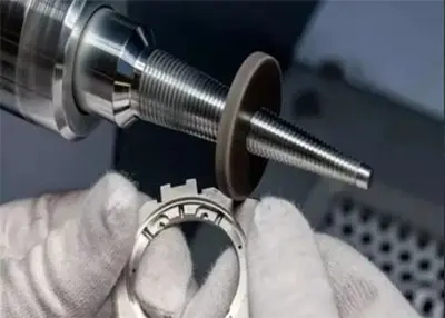
Drilling and tapping go closely together. In many shops, internal threads are cut with taps. These look a bit like screws with teeth and are "cut" into a pre-drilled core hole. We use a more modern process for threads and interpolate the thread profile with a so-called thread milling cutter, thus creating an accurate thread. With one and the same milling tool, threads of any size can be cut with the same pitch (number of threads per millimeter). This results in shorter setup and production times. Thus, with only one tool set, UNC, UNF threads from 2 to 1/2 inch and metric threads from M2 to M12 can be produced.

This design tip looks at various CNC machining options, including the 5-axis machining shown here (also referred to as "3+2" axis machining). This illustration shows the largest part dimensions of a 74 mm wide by 51 mm high part with optimal material usage.
Need to have the part number, a designation or a logo milled into your parts? The cutter packages at Richconn can mill almost any text you need, provided the spacing between characters and the line width is at least 0.5 mm. Also, text should be recessed and not raised. Sans-serif fonts such as Arial or Verdana with a size of at least 20 point are recommended.
All our milling cutter packages contain carbide milling tools. This particularly stiff material ensures maximum life of the cutting tools and highest productivity with minimal wear. However, even the hardest tools wear out, as do workpieces made of metal or especially plastic. For this reason, rib depth and geometry ranges depend heavily on the individual part geometry as well as the milling cutter package used. For example, the minimum thickness at Richconn is 0.5 mm, and the maximum depth is 51 mm. However, this does not mean that these dimensions must be suitable for the fins of a heat sink.

In addition to our wide range of CNC milling services, we also offer CNC lathes with driven tools. The tool sets used on these lathes are similar to those used in our milling centers, but we do not currently use them to machine plastic parts. Off-center holes, slots, flats and other features can be worked with them parallel or perpendicular (axial or radial) to the "long" axis (Z-axis) of the turned part, generally following the same design rules as the orthogonal parts produced in our milling centers. The difference is in the shape of the semi-finished part and not in the tool set. Turned parts such as shafts and pistons are made from round stock, while milled parts such as manifold blocks, instrument housings and valve covers usually come from cube or cuboid shaped blocks. However, as you will see in a moment, we have overcome these limitations as well.
Richconn distinguishes between two "types" of milling. In 3-axis milling, the blank or workpiece is clamped at the bottom while machining is performed from the top. Separate clamping is therefore required for the other sides of the workpiece. For parts larger than 254 mm x 178 mm, only the top and bottom sides can be machined - clamping for lateral machining is not possible! In indexed milling, on the other hand, up to five sides of a workpiece can be machined without reclamping. In 5-axis milling, the part can be tilted at any angle (even compound) by up to 90 degrees, allowing complex, non-orthogonal positioning.
The cutter packages used are identical in both cases. The difference lies in the blank. As with our lathes, bar stock is used for 5 axis milling, which leads to some interesting mathematical discussions about the size, geometry and positioning of the workpiece within the stock volume - perhaps you remember the Pythagorean theorem? To see some examples, you can either study the diagrams, or simply upload your CAD model online at https://www.richconn-cnc.com/ for a real-world example.
We will be happy to answer any questions you may have. For individual assistance, please contact our staff at +86-0755-28025755 or sales@richconn.com.cn.
 How to Measure Surface Roughness?August 2, 2023In order to ensure the optimal quality of parts, the surface of components after manufacturing applications must be maintained within the desired range of roughness. Surface treatment plays a critical...view
 Machining outsourcing: advantages and disadvantages of full analysisNovember 16, 2023Machining Outsourcing is a common business model in the manufacturing industry that takes a company's machining needs and gives them to another outside supplier that specializes in machining.view
 One Article Tells You What CNC Machining isSeptember 27, 2023The term CNC stands for "Computer Numerical Control" and CNC machining is defined as a subtractive manufacturing process that typically employs computer-controlled and machine tools to remove layers of material from a stock part (known as a blank or workpiece) and produce a custom-designed part.view
 Precautions for Using CNC TurningApril 25, 2023Turning is a cutting method that uses the rotation of the workpiece relative to the tool on a lathe to perform cutting operations. CNC turning allows the workpiece rather than the tool to provide most...view
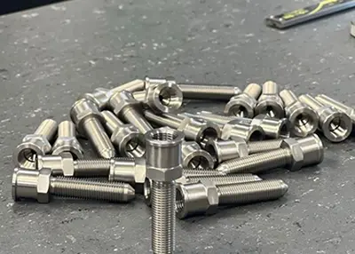 How Much Do You Know About Stainless Steel Knowledge?October 23, 2023Steel, is a generic term for iron-carbon alloys that contain between 0.02% and 2.11% carbon. When the carbon content is greater than 2.11%, it is referred to as pure iron. The chemical composition of steel can vary greatly, and steel containing only carbon is known as carbon or plain steel.view
 Case Study 2023: Improving the Yield of Precision Mandrel Parts ProductsDecember 22, 2023Key production process design and high-quality processing give us the basic characteristics that customers like, and we can also provide you with the services you need.view
 EN
EN
 ru
ru 


")