Engineering drawings are essential tools for engineers to communicate, but not always easy to decipher. Understanding the basics of engineering drawing is a good first step, allowing you to communicate the intent of your CNC machined parts design. Most rapid prototyping customers upload design files and drawings for a better understanding of requirements, but not all engineers are well-trained to drawing engineering clearly, which can cause challenges for manufacturers and have negative impacts on costs, lead time, and specification clarity.
This guide aims to introduce technical drawing basics and provide 8 important tips for creating better engineering drawings, so that you can learn to create them effectively, ensuring clear communication of your unique ideas and requirements, and saving time and money.
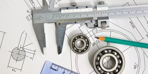
Engineering drawing, also termed mechanical engineering drawing, is a kind of technical drawing with the objective of precisely and distinctly capturing the geometric characteristics and components of engineering products, as well as describing their shapes, sizes, and specifications. It functions as a graphical language specifically for engineers and other associated technical personnel, offering detailed information regarding an object's dimensions, forms, surface types, and materials. The drawing encompasses a detailed description of the manufacturing process and a collection of projections presenting diverse angles of the components. It can manifest in multiple forms and is applied in diverse fields such as providing building drawings for civil engineers and generating machine drawings for mechanical engineers. Essentially, it represents the craft of accurately depicting a real or imagined object on paper by employing graphics, symbols, letters, and numbers with the assistance of engineering drawing tools, with the ultimate aim of guaranteeing that the produced components fulfill specific requirements.
In general, it is difficult and complex to explain certain specific engineering requirements verbally. In such a case, an engineering drawing with an appropriate size and proper scale can facilitate the technician to comprehend and attain the design intention. The engineering drawing of a single part presents a visual representation of the part's structure, dimensions, tolerances, and other necessities. A single-part drawing is commonly utilized as the unit for processing in the manufacturing sector. Moreover, an engineer can employ an assembly drawing to demonstrate a machine or equipment assembled from numerous parts to achieve a specific function. Assembly drawings are often employed to verify that the actual fabrication of individual parts satisfies the assembly requirements.
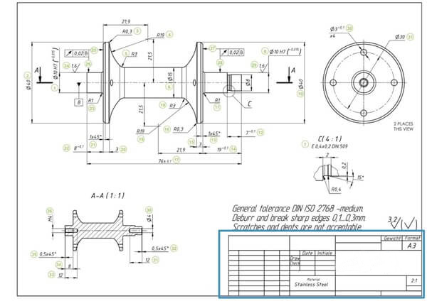
In the past years, all that was obtainable were drawing boards, papers, rulers, calipers, and the like. Though these instruments are still accessible nowadays for manual drawings, such drawings are not appropriate for present-day manufacturing. The reason for this is that the majority of CNC systems nowadays can read the information directly from the files. Consequently, they can readily produce a cutting program as needed. Handmade drawings would merely make this more troublesome for engineers. The emergence of computer-aided design (CAD) software has made matters much simpler. This software possesses several advantages over manual drawings. You can utilize CAD to create drawings from the beginning. Nevertheless, the simpler option would be initially to make a 3D model, and then you can generate your drawings therefrom. Basically, all you need to do is to incorporate the dimension. The CAD program generates views with merely a few clicks. The 3D models will make it much easier to update the drawings for revisions. Once you produce excellent engineering drawings that display your specific requirements, you can upload them to the Richconn platform, which offers professional prototyping manufacturing services.
Drawings play an important role in engineering production. To create the most suitable example engineering drawing for production, it is necessary to have a good understanding of the basic knowledge of technical drawing. A single drawing types engineering is composed of several elements, and there are some variations. In this section, we will study the components that make up the engineering drawing together in detail, hoping that this can help you read the engineering drawing.
It should be noted that all the line types engineering drawing are of the same kind. Various options are provided to show the hidden and visible edges of the parts.
Continuous Line
The most common type of line is the continuous line, also known as the drawing line. It represents the physical boundaries of an object. In other words, a continuous line is used to draw the object. The thickness of the line varies, with the inner lines being thinner and the outer contours using thicker lines.
Center Line
The center line can display the parts with holes and symmetrical features. Symmetry can reduce the number of dimensions in a drawing, making it more visually appealing and easier to understand for the reader.
Hidden Line
The hidden line is another type of line used in mechanical drawing. Hidden line in engineering drawing can show something that would otherwise not be visible in the drawing. For instance, the hidden lines engineering drawing can show the length of the interior step on a part without using a section or cutaway view.
Dimension and Extension Line
The extension line describes the object being measured. The dimension line has two arrowheads between the extension lines and the measurement above (or inside) the line.
Engineering drawings include various types of views, each serving a specific function. The addition of views should follow the same logic as dimensioning, and only those views in engineering drawing that contribute to the overall understanding of the design should be included.
Orthographic View
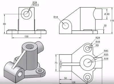
The orthographic view forms the essence of an engineering drawing. It presents a three-dimensional object in two-dimensional form using an orthographic projection. This ensures that all the necessary information for part manufacturing is conveyed through a two-dimensional view, without any length distortion.
In a multi-view drawing, three different views, such as the front view, top view, and side view, can be used to convey all the required information. It is possible that several additional engineering drawing views may be needed to display all the information. However, simplicity is often preferred.
Isometric View
Isometric drawings depict three-dimensional parts. All vertical lines remain vertical, while parallel lines are presented at a 30-degree angle. The lengths of vertical and parallel lines are accurate. Thus, using a ruler and the scaling of the drawing, one can easily measure the length from a paper drawing. However, this is not the case with angled lines. With this type of view, engineers rely on dimensions rather than optical illusions.
Section View
A section view readily reveals certain characteristics of a part that are not immediately apparent. The cross-section is preferred over hidden lines in mechanical engineering drawings as it offers greater clarity. The cross-hatching feature serves as an indicator of the cross-sectional view.
Detail View
The detail view provides a magnified view of specific sections within a larger view. When a large part contains numerous crucial dimensions in a small area, the detail view is ideal. It enhances the readability of the measurements.
Cutout View
The cutout view utilizes the same image as the section view, with one exception: the side view incorporates cutouts. Cutouts can help reduce the number of distinct engineer drawing views on a single drawing. Consequently, the section view can be easily deleted, and all required dimensions can be added to the cutouts.
Auxiliary View
The auxiliary view is an orthographic view used to represent non-horizontal or non-vertical planes. It displays inclined surfaces without any distortions.
As mentioned earlier, new CNC machines can directly read dimensions from the line. Some critical pieces of information might be missing from CAD models, such as tolerancing GD&T and geometric dimensioning.
The correct engineering drawing dimensions always ensure a long service life of components with less maintenance. You can automatically obtain dimensions by clicking the measure button. However, including engineering tolerances requires manual operation.
Here are 8 tips for creating engineer drawing examples that will help you communicate the critical needs of the parts more effectively while also saving you time and money.
Tip 1: Only dimension critical and measurable features.
All dimensions in CNC machining can be derived from the 3D model, so only include critical inspection dimensions and threading information on the 2D drawing.
Tip 2: Communicate hole tapping needs with thread size and depth.
Because thread depth is difficult to measure precisely, the depth call-out should always be taken as the minimum.
Tip 3: Consolidate call-outs for features that exist in multiple views.
Only give a dimension to one of the features in a view and name the dimension "#X DIM" to indicate that the feature exists X times in the view.
Tip 4: Clearly communicate the assembly intent of crucial features.
If the production involves the machining of an entire assembly, provide an assembly drawing or instructions. You can also offer part numbers for your machinists to look up when installing off-the-shelf hardware.
Tip 5: Provide part numbers and suppliers for hardware installation.
If hardware installation is required, include the part number and supplier on the drawing, which is very important.
Tip 6: There's no need to include optional secondary operation call-outs on the drawing.
If post-processing such as polishing and anodizing is not critical, it's advisable to request a separate price and lead time. This way, you can know the additional cost and time. Similarly, if you're unsure about the type of material to use, leave it off the drawing to avoid confusion in production.
Tip 7: Avoid over-dimensioning or over-tolerancing in your designs.
Only a few features of a part are usually essential to its function, so you want the machinist to focus more on these features. Over-dimensioning may lose key needs in the noise, so only allocate tolerances to mission-critical features.
Tip 8: The tolerance must fall within standard accuracy levels.
It's essential to provide the appropriate level of tolerance for your material. Don't require tolerances below the accuracy capabilities of standard hand metrology tools. Consequently, it's necessary to research the starting measurements for your preferred machine shop.
Engineering drawings are a graphical language used to express engineering design ideas and details, and they are an important tool for engineers to carry out design, manufacturing, and maintenance. Engineering drawings follow some international or national standards for engineering drawings and specifications to ensure the accuracy, consistency, and readability of the engineering drawings, which is important to learn how to read engineering drawings correctly.
If you’re looking for some professional suggestions on creating a perfect engineering drawing, Richconn must be your reliable choice! Richcoon, with its advanced equipment, full automation, and a professional team with extensive experience, specializes in precision parts manufacturing. Its digital management system improves efficiency and quality, while the flexible supply chain helps control costs and risks. Try contacting Richconn for free support⬇⬇⬇
 3D Printed Car Parts: All About 3D Printing in the Automotive IndustryMarch 1, 20243D printing for car parts caters to the personalization needs of many companies without compromising quality. Find out everything you need about 3D printed car parts here.view
 What are the machining processes?November 16, 2023Machining processes are a key manufacturing method used to transform raw materials into desired parts and products. These processes include milling, turning, drilling, grinding, reaming, stamping, forging, injection molding, EDM, heat treatment, welding, stretch molding, powder metallurgy and 3D printing. The following are some common machining processes:view
 Protect, Enhance, Beautify: The Versatility of Blackening Surface TreatmentsDecember 4, 2023Surface treatments play a vital role in maintaining and enhancing the durability and appearance of various materials. Whether it is for aesthetic purposes, rust prevention, or to improve wear resistan...view
 PVD Surface Treatment: Achieving Durability and AestheticsAugust 14, 2023PVD (Physical Vapor Deposition) surface treatment process is usually used to create hard, durable and beautiful surfaces. It involves applying a thin layer of metal or ceramic coating onto an object t...view
 What is Precision Grinding & Types, Materials, ProcessesNovember 27, 2023The so-called precision grinding process is to utilize fine-grained abrasive grains and micro-powder to process ferrous metals, hard and brittle materials, etc., in order to obtain high machining accuracy and low surface roughness values.view
 Climb vs Conventional Milling: What Are the Differences?March 20, 2024Understanding climb vs conventional milling clearly is one way to help you choose the right milling process. Here is a comprehensive guide to their differences.view